Table of Contents
Advertisement
Quick Links
Advertisement
Table of Contents

Related Manuals for Motic AE2000MET


Summary of Contents for Motic AE2000MET
- Page 2 Therefore, all descriptions and illustrations in this instruction manual, including all specifications are subject to change without notice. Hereby, we deeply appreciate that you choose MOTIC instrument, your satisfactions is our best payback!
-
Page 3: Table Of Contents
CONTENT NOMENCLATURE 1.1 Application 1.2 Nomenclature 1.3 Technical data SETTING-UP THE INSTRUMENT 2.1 Working Environment 2.2 Input voltage and power ASSEMBLING THE MICROSCOPE 3.1 Illumination (Halogen) 3.2 Installing the Lamp house 3.3 Installing the Objectives 3.4 Inserting the Eyepieces 3.5 Installing the Analyzer and Polarizer 3.6 Power cord 4. - Page 4 5. PHOTOMICROGRAPHIC PROCEDURE ( TRINOCULAR ONLY) TROUBLESHOOTING TABLE 6.1 Optical and Operating Problems 6.2 Electrical CARE AND MAINTENANCE 7.1 Lenses and Filters 7.2 Cleaning of Painted or Plastic Components 7.3 When Not in Use 7.4 Warning Label...
-
Page 5: Nomenclature
The overall optical performance of the AE2000MET series is superb and unique for projecting the real micro world for you, via using a new generation of BD and BF metallurgical plan objectives be made of high-quality glass and upgrade anti-reflex coating tech, whatever be used for analysis or quality control in all industry. -
Page 6: Nomenclature
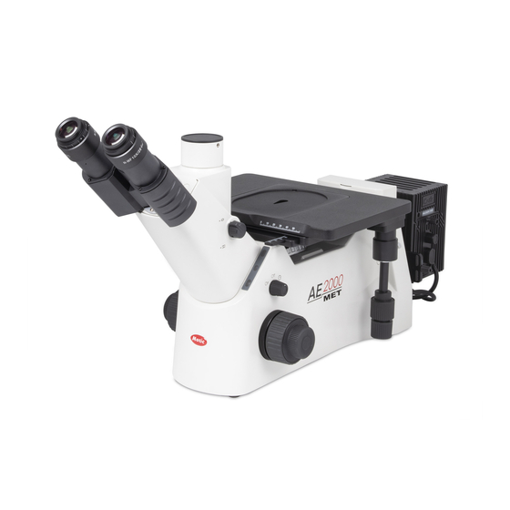
1.2 Nomenclature 1.2.1 AE2000MET Trinocular left side view (Fig.1) -
Page 7: Technical Data
1.2.2 AE2000MET Trinocular right side view (Fig.2) Note: Please be aware the accessories are presented in above or following figure, such as: Objectives, Illuminations, Polariser/Analyser, color filter etc., just for demonstration purpose of operations, please contact your local vendor or seller for more details. -
Page 8: Setting-Up The Instrument
2. SETTING-UP THE INSTRUMENT 2.1 Working Environment The location should be free from dust, moisture, chemical vapours and from mechanical vibrations. Don't locate the instrument in bright or direct ambient light, in front of a lamp, or a will-lit bright wall. Best image will be achieved without significant ambient light. - Page 9 100W Halogen Rating: Power Adaptor Input: 100-240Vac, 50-60Hz, 1.6A Main Unit Input: 15Vdc, 4.2A Halogen Lamp Input: 12Vdc, 100W Attention: The plug of the power adaptor is the "disconnect device" for whole unit. To save energy we recommend to unplug the instrument when not in use. The device is specified to connect to the following power adaptor: SINPRO ELECTRONICS CO LTD, Model: IPU63-106 Input: 100-240Vac, 50-60Hz, 1.6A...
-
Page 10: Assembling The Microscope
3. ASSEMBLING THE MICROSCOPE 3.1 Illumination (Halogen) 3.1.1 Halogen bulb The quartz halogen bulb, used as a light source, has higher luminance and colour temperature than conventional tungsten lamps. The luminance of halogen bulb is approximately four times brighter than the conventional tungsten lamps. - Page 11 (Fig.3-1) (Fig.3-2) (Fig.3-3) (Fig.3-4)
- Page 12 100W Halogen The applicable halogen bulbs are the 12V 100W HAL high-intensity bulb. (Osram, model: 64625 HLX) In order to prevent electric shock always turn the power switch off and unplug the power cord before installing or replacing the lamp. ...
-
Page 13: Installing The Lamp House
Fig.4-5 Fig.4-6 3.2 Installing the Lamp house 50W Halogen Loosen the round dovetail clamp screw (2.5mm Allen key screw) on the microscope stand, insert the lamp house into the round dovetail on the microscope stand. (Fig.5-1) Tighten the clamp screw to secure the lamp house in place (Fig.5-2). ... - Page 14 100W Halogen Loosen the round dovetail clamp screw (2.5mm Allen key screw) on the microscope stand, insert the lamp house into the round dovetail on the microscope stand. (Fig.6-1) Tighten the clamp screw to secure the lamp house in place (Fig.6-2). ...
-
Page 15: Installing The Objectives
3.3 Installing the Objectives Hold an objective and screw it in the nosepiece thread hole till its limited position gradually then revolve the nosepiece in clockwise direction. install the next objective in blank thread hole as needs, following the above approach. (Fig.7) Caution: to guarantee the precision please use even force to screw objective in thread holes, any violation may influence the quality of imaging and... -
Page 16: Installing The Analyzer And Polarizer
3.5 Installing the Analyzer and Polarizer Make sure analyzer or polarizer clean Insert the analyzer (Fig.9-1) or polarizer (Fig.9-2) into the optical path. (Fig.9-1) (Fig.9-2) 3.6 Power cord Make sure the power cord complying with the local power supply specification ... -
Page 17: Microscope Handling
4. MICROSCOPE HANDLING 4.1 Interpupillary Distance Adjustment Before adjusting the interpupillary distance, bring a specimen into focus using the 10x objective. Adjust the interpupillary distance so that both the right and left field of view become one (Fig.11). This adjustment will enable the user to observe the specimen with both eyes. -
Page 18: Coarse And Fine Focusing
4.3 Coarse and fine focusing For focusing of the instrument please use the coarse and fine focus knobs on the left and right side of the microscope stand. (Fig.13-1) The direction of vertical movement of the revolving nosepiece corresponds to the turning direction of the focus knob. -
Page 19: Adjust The Aperture Diaphragm
4.6 Align up Field Diaphragm and Aperture Diaphragm Before start to use microscope to observe the specimen or sample, please do make sure the Field Diaphragm center and Aperture Diaphragm center be coaxial seriously, to fully activate MOTIC CCIS infinity optic system performance ... -
Page 20: Use Of Polariser And Analyser
(Fig.15-1) (Fig.15-2) (Fig.16-1) (Fig.16-2) 4.7 Use of Polariser and Analyser Insert the polariser (marked with “P”) into the slot. Insert the Analyser (marked with “A”) into the slot. Analyser is rotatable and the color of specimen/ Sample with polarization will be changed when rotating. -
Page 21: Bright Field Observation
Open the aperture diaphragm fully. Pull the draw-rod in the DF position. (Fig.19) AE2000MET BD series standard configuration have equipped with LM BD objective, which can perform bright field observation and dark field observation conveniently, no need to change the objective... -
Page 22: Polarizing Observation
4.10 Polarizing Observation Insert the polariser (marked with “P”) into the slot. Insert the Analyser (marked with “A”) into the slot. Rotate the analyser according to demands. (Fig.20) Note: Before inserting Polariser and Analyser in slot please make sure the filter surface is dust-free, for cleaning method please refer to item 7. -
Page 23: Auto/ Off/ On Switch Function
Put the filter in slider (Fig.21-1) (Fig.21-1) Insert the slider back in slot (Fig.21-2 and 21-3) (Fig.21-2) (Fig.21-3) Note: Before inserting filter in slot, please make sure the filter surface is dust-free, for cleaning method please refer to item 7. “CARE AND MAINTENANCE” Before starting to observation, please make sure item 4.6 has been set up properly It is in the same way to insert the slider back in slot of 50W lamp house 4.13 Auto/ Off/ On switch function... -
Page 24: Stage With Scale For Movement Reference
(Fig.22-1) (Fig.22-2) The power control knob is located above the right focusing knob. (Fig.22-1) When “ Auto” is selected (Fig.22-2), the blue pilot lamp indicates that an IR-sensor is activated (Fig.22-3). If no user is detected in front of the microscope, the microscope illumination will automatically switch off after 15 minutes. -
Page 25: Photomicrographic Procedure (Trinocular Only)
5. PHOTOMICROGRAPHIC PROCEDURE (TRINOCULAR ONLY) To ensure vibration free operation, set the microscope on a sturdy vibration free table or a bench with a vibration proof device. Turn the beam splitter knob (Fig.24) of the eyepiece tube to the “need icon”... -
Page 26: Troubleshooting Table
MOTIC microscope kindly. 6.1 Optical and Operating Problems Problem... -
Page 27: Electrical
6.2 Electrical Problem Possible Cause Power supply not plugged in right position of socket Lamp not installed properly Lamp does not light User left more than 15 minutes under auto mode Lamp burnt out or end of life Inadequate brightness Specified lamp not being used Lamp blows out immediately Specified lamp not being used... -
Page 28: Care And Maintenance
7. CARE AND MAINTENANCE 7.1 Lenses and Filters To clean lens surfaces or filters, first remove dust using an air blower. If dust still exists, use a soft/ clean brush or gauze. A soft gauze or lens tissue lightly moistened with the mixture of alcohol and ether ( ratio:alcohol: 3 and ether: 7) should only be used to remove grease or fingerprints. -
Page 29: Warning Label
7.4 Warning Label The following warning labels (or symbols) are found on the microscope, study the meaning of the warning labels (or symbols) and always use the equipment in the safest possible manner. Warning Label / Symbol Explanation Indicates that the surface becomes hot, and should not be touched with bare hands. - Page 30 Fax: 86-0592-562 7855 © 2007-2012 Motic China Group Co., Ltd. All rights reserved. Motic is a registered trademark and service mark of Motic China Group Co., Ltd. Microsoft Windows logo is a registered trademark of Microsoft Corporation. All other trademarks are the property of their respective owners.
Need help?
Do you have a question about the AE2000MET and is the answer not in the manual?
Questions and answers