Sign In
Upload
Download
Table of Contents
Contents
Add to my manuals
Delete from my manuals
Share
URL of this page:
HTML Link:
Bookmark this page
Add
Manual will be automatically added to "My Manuals"
Print this page
×
Bookmark added
×
Added to my manuals
Manuals
Brands
Motic Manuals
Microscope
AE30
Instruction manual
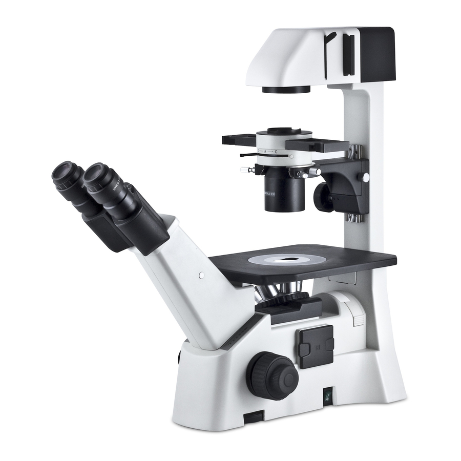
Motic AE30 Instruction Manual
Inverted microscope
Hide thumbs
1
2
Table Of Contents
3
4
5
6
7
8
9
10
11
12
13
14
15
16
17
page
of
17
Go
/
17
Contents
Table of Contents
Troubleshooting
Bookmarks
Table of Contents
Table of Contents
I Nomenclature
Specification
Setting-Up the Instrument
Assembling the Microscope Input Voltage
Installing the Lamp
Mounting the Condenser
Installing the Objectives
Mechanical Stage
Mounting the Eyepieces
Microscopic Procedure Interpupillary Disatance Adjustment
Diopter Adjustment
Centering the Condenser
Centering the Lamp
Brightfield Microscopy
Phase-Contrast Microscopy
Photomicrographic Procedure
Troubleshooting Table
Care and Maintenance
Lenses and Filters
Cleaning of Painted or Plastic Components
When Not in Use
Warning Lable
Advertisement
Quick Links
1
Specification
2
Setting-Up the Instrument
3
Installing the Lamp
4
Photomicrographic Procedure
5
Troubleshooting Table
6
Care and Maintenance
Download this manual
Table of
Contents
Previous
Page
Next
Page
1
2
3
4
5
Advertisement
Table of Contents
Need help?
Do you have a question about the AE30 and is the answer not in the manual?
Ask a question
Questions and answers
Related Manuals for Motic AE30
Microscope motic AE30-31 Instruction Manual
Episcopic-fluorescence attachment ef-inv-ll inverted microscope (45 pages)
Microscope Motic AE21 Instruction Manual
Inverted microscope (15 pages)
Microscope Motic AE20 Instruction Manual
Inverted microscope (15 pages)
Microscope Motic AE2000 BIN Instruction Manual
Ae2000 series (27 pages)
Microscope Motic AE2000 Instruction Manual
Inverted microscope ae2000 series (28 pages)
Microscope Motic AE31 Instruction Manual
Inverted microscope (17 pages)
Microscope Motic AE2000MET Instruction Manual
Metallurgy microscope (30 pages)
Microscope Motic PSM1000 Series User Manual
Microscope unit (18 pages)
Microscope Motic AE31E Series Instruction Manual
Inverted microscope (29 pages)
Microscope Motic B3 Series Instruction Manual
(13 pages)
Microscope Motic BA310 Pol Instruction Manual
Polarizing microscope (30 pages)
Microscope Motic SMZ168 Series Instruction Manual
(11 pages)
Microscope Motic SMZ168 Series Instruction Manual
(34 pages)
Microscope Motic SMZ-140 Instruction Manual
Stereo zoom microscopes (16 pages)
Microscope Motic BA210 series Instruction Manual
Biological (25 pages)
Microscope Motic B1 Series Instruction Manual
Biological microscope (26 pages)
This manual is also suitable for:
Ae31
Table of Contents
Print
Rename the bookmark
Delete bookmark?
Delete from my manuals?
Login
Sign In
OR
Sign in with Facebook
Sign in with Google
Upload manual
Upload from disk
Upload from URL


Need help?
Do you have a question about the AE30 and is the answer not in the manual?
Questions and answers