Table of Contents
Advertisement
Quick Links
Advertisement
Table of Contents

Related Manuals for Motic AE2000 BIN


Summary of Contents for Motic AE2000 BIN
- Page 2 We are constantly endeavouring to improve our instruments and to adapt them to the requirements of modern research techniques and testing methods. This involves modification to the mechanical structure and optical design of our instruments. Therefore, all descriptions and illustrations in this instruction manual, including all specifications are subject to change without notice.
-
Page 3: Table Of Contents
Content Nomenclature 1. Application 2. Nomenclature 3. Technical data II. Setting-up the Instrument 1. Working Environment 2. Input voltage and power III. Assembling the Microscope 1. Installing the bulb 1.1 Halogen bulb 1.2 LED module 2. Filter Holder 3. Mounting the Condenser 4. - Page 4 VI. Troubleshooting Table 1. Optical and Operating Problems 2. Electrical VII. Care and Maintenance 1. Lenses and Filters 2. Cleaning of Painted or Plastic Components 3. When Not in Use 4. Warning Label...
-
Page 5: Nomenclature
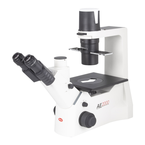
I. Nomenclature 1. Application The new Inverted microscope AE2000 is representing the ideal instrument for living cells observation and other microbiological samples. Due to our Colour Corrected Infinity Optics (CCIS) the AE2000 offers superior image quality combined with excellent mechanical performance. Daily work is facilitated by a number of ergonomic features. - Page 6 Model AE2000...
- Page 7 Model AE2000 TRI Model AE2000 Ergo...
-
Page 8: Technical Data
3. Technical data Technical data AE2000 BIN AE2000 TRI AE2000 Ergo Optical system Color Corrected Infinity Optics (CCIS) Total Magnification 40X - 400X 360° Swiveling Siedentopf with upper and lower position: upper position offers approx. 40 mm extra viewing height... -
Page 9: Setting-Up The Instrument
II. Setting-up the Instrument 1. Working Environment The location should be free from dust, moisture, chemical vapours and from mechanical vibrations. Don't locate the instrument in bright or direct ambient light, in front of a lamp, or a will-lit bright wall. Best image will be achieved without significant ambient light. - Page 10 Attention: The plug of the power adaptor is the "disconnect device" for whole unit. To save energy we recommend to unplug the instrument when not in use. This device complies with Part 15 of the FCC Rules. Operation is subject to the following two conditions: (1) This device may not cause harmful interference, and (2) this device must accept any interference received, including interference that may cause undesired operation.
-
Page 11: Assembling The Microscope
III. Assembling the Microscope 1. Installing the bulb In order to prevent electric shock always turn the power switch off (Fig.1) and unplug the power cord (Fig.2) before replacing the bulb. To remove lamphouse cover, press down lightly (1) and rotate counter clockwise (2). (Fig.3) Power Switch (Fig.1) Power Cord (Fig.2) Lamp house Cover (Fig.3) - Page 12 (Fig.7) (LED module) Firmly insert the LED module into the socket pinholes until it reaches the limit. This is a Motic patent design to exchange LED module and halogen bulb on the same socket directly. After the LED module installation (Fig.6), secure it with the clamp screw by 1.5mm hexagonal screwdriver supplied with the microscope.
-
Page 13: Halogen Bulb
(Fig.8) 1.1 Halogen bulb The quartz halogen bulb, used as a light source, has higher luminance and colour temperature than conventional tungsten lamps. The luminance of halogen bulb is approximately four times brighter than the conventional tungsten lamps. As long as the lamp voltage is kept constant, the halogen lamp maintains the same level of brightness and colour temperature regardless of whether it is new or nearing the end of its life span. -
Page 14: Mounting The Condenser
3. Mounting the Condenser Mount the condenser on the dovetail mount of the condenser holder (Fig.11) with the aperture diaphragm lever facing the front. Secure it with the clamp screw by the 2.5mm hexagonal screwdriver (supplied with the microscope; Fig.12) (Fig.11) (Fig.12) If Phase contrast is to be used, insert the Phase slider into the slot of the condenser. -
Page 15: Mechanical Stage
An attachable mechanical stage is available as an option. This stage allows the precise movement of common vessels for cell culture. For choosing the respective vessel carrier, please contact your local Motic supplier. Secure the mechanical stage to the AE2000 plain stage using the two mounting screws (Fig.16) located beneath the stage on the right side (user facing the front of the instrument). -
Page 16: Inserting The Eyepieces
6. Inserting the Eyepieces Remove the dust caps from the eyepiece tubes. Use the same magnification eyepieces for both the eyes. Insert each eyepiece into the eyepiece sleeve by a twisting movement. (Fig.17) Should the rubber eye guards are to be used,fit them in the groove around the eyepiece. (Fig.17) -
Page 17: Microscope Handling
IV. Microscope Handling 1. Interpupillary Distance Adjustment Before adjusting the interpupillary distance, bring a specimen into focus using the 10x objective. Adjust the interpupillary distance so that both the right and left field of view become one. This adjustment will enable the user to observe the specimen with both eyes. 2. -
Page 18: Coarse And Fine Focusing
3.Coarse and fine focusing For focusing of the instrument please use the coarse and fine focus knobs on the left and right side of the microscope stand. The direction of vertical movement of the revolving nosepiece corresponds to the turning direction of the focus knobs. -
Page 19: Changing Between Halogen And Led Illumination
5. Changing between Halogen and LED illumination Attention: Unplug the plug-in power unit from the microscope to avoid any risk of electric shock. Before replacing the bulb/changing to LED please wait for a sufficient cool-down time of the bulb. Press down lightly the lamp house cover and rotate it counter clockwise for removal. (Fig.21) (Fig.21) Remove the bulb from the socket pinholes. -
Page 20: Brightfield Microscopy
6. Brightfield Microscopy Set the Phase slider to the centre position (in standard configuration this position does not contain an illumination annulus) (Fig 24). In case all 3 positions of the slider are occupied due to personal setup of the microscope, pull out the complete slider. Bring the specimen into focus. - Page 21 Remove one eyepiece from the eyepiece tube and insert the phase centering telescope instead. (Fig.25) Loosen the fixing screw on the centering telescope. By pulling out the inner part of the centering telescope, you may focus on a dark ring inside the phase contrast objective (this circular phase plate is responsible for the phase effect).
- Page 22 (Fig.26) (Fig.27) To achieve maximum contrast in phase contrast a Green Interference filter is recommended. It may be inserted in the filter mount of the condenser carrier. To insert/replace an annular diaphragm take care the diaphragm has got the correct orientation (Fig.28).
-
Page 23: Filter Selection
8. Filter selection Filter holder can hold two filters Filter type Procedure ND (Neutral Density) filter For intensity adjustment in photomicrography For phase contrast and contrast adjustment with GIF (Green Interference) filter 546nm black and white film For general microscopy and colour Blue filter photomicrography 9. -
Page 24: Photomicrographic Procedure (Only On Ae2000 Tri)
V. Photomicrographic Procedure (Only on AE2000 TRI) To ensure vibration free operation, set the microscope on a sturdy vibration free table or a bench with a vibration proof device. Turn the beam splitter knob of the eyepiece tube to the “photo position” (Fig.31). The photo exit is activated, 80% of the light will enter the camera. -
Page 25: Troubleshooting Table
VI. Troubleshooting Table As you use your microscope, you may occasionally experience a problem. The troubleshooting table below contains the most frequently encountered problems and their possible causes. 1. Optical and Operating Problems Problem Possible Cause Bulb not installed properly Filter slider in intermediate position Phase slider not in click-stop position Incorrect condenser mounting... -
Page 26: Care And Maintenance
VII. Care and Maintenance 1. Lenses and Filters To clean lens surfaces or filters, first remove dust using an air blower. If dust still persists, use a soft / clean brush or gauze. A soft gauze or lens tissue lightly moistened with the mixture of alcohol and ether ( ratio: alcohol : 3 and ether: 7) should only be used to remove grease or fingerprints. -
Page 27: Warning Label
CAUTION! Risk of danger. (See user manual) Proper handling of the microscope will ensure years of trouble free service. If repair become necessary, please contact your Motic agency or our Technical Service directly.
Need help?
Do you have a question about the AE2000 BIN and is the answer not in the manual?
Questions and answers