Table of Contents
Advertisement
Quick Links
Advertisement
Table of Contents

Related Manuals for Motic AE31E Series


Summary of Contents for Motic AE31E Series
- Page 2 We are constantly endeavouring to improve our instruments and to adapt them to the requirements of modern research techniques and testing methods. This involves modification to the mechanical structure and optical design of our instruments. Therefore, all descriptions and illustrations in this instruction manual, including all specifications are subject to change without notice.
-
Page 3: Table Of Contents
Content Nomenclature 1.1 Application 1.2 Nomenclature 1.3 Technical data Setting-up the Instrument 2.1 Working Environment 2.2 Input voltage and power 2.3 Illumination 2.3.1 Halogen bulb 2.3.2 LED module Assembling the Microscope 3.1 Installing the bulb/ LED module 3.1.1 30W Halogen 3.1.2 100W Halogen 3.1.3 LED module 3.2 Filter Holder... - Page 4 Photomicrographic Procedure (Only on AE31E TRI) Troubleshooting Table 6.1 Optical and Operating Problems 6.2 Electrical Care and Maintenance 7.1 Lenses and Filters 7.2 Cleaning of Painted or Plastic Components 7.3 When Not in Use 7.4 Warning Label...
-
Page 5: Nomenclature
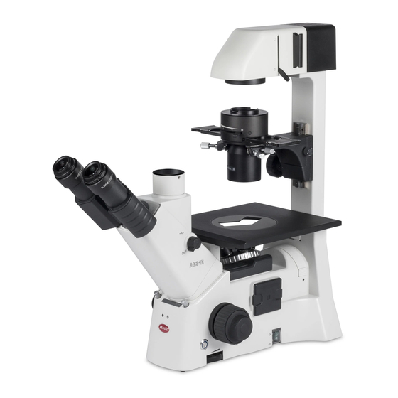
1. Nomenclature 1.1 Application The new Inverted microscope AE31E is representing the ideal instrument for living cells observation and other microbiological samples. Due to our Colour Corrected Infinity Optics (CCIS) the AE31E offers superior image quality combined with excellent mechanical performance. Daily work is facilitated by a number of ergonomic features. -
Page 6: Nomenclature
1.2 Nomenclature Model AE31E TRI (Fig.1) - Page 7 Model AE31E TRI (Fig.2)
-
Page 8: Technical Data
1.3 Technical data Technical data AE31E BIN AE31E TRI Optical system Color Corrected Infinity Optics (CCIS) Total Magnification 40X - 400X 360° Swiveling Siedentopf with upper and lower position: upper position offers approx. 40 mm extra viewing height Eyepiece tubes Interpupillary distance: 48 mm to 75 mm Binocular 45°... -
Page 9: Setting-Up The Instrument
2. Setting-up the Instrument 2.1 Working Environment The location should be free from dust, moisture, chemical vapours and free of mechanical vibrations. Don't locate the instrument in bright or direct ambient light, in front of a lamp, or a bright light wall. Best imagequality will be achieved in a surrounding surrounding with low ambient light. -
Page 10: Illumination
100W Halogen bulb Input : 100-240V~, 120W, 50-60Hz Bulb: 12VDC 100W Halogen Fuse : 250V T2.5A (If the original fuse is blown, please replace with specified fuse) LED module Input: 100-240V~, 80VA, 50-60Hz LED: 3.4V Fuse: 250V T2.5A (If the original fuse is blown, please replace with specified fuse) ... -
Page 11: Assembling The Microscope
3. Assembling the Microscope 3.1 Installing the bulb/ LED module 3.1.1 30W Halogen In order to prevent electric shock always turn the on/off switch off (Fig.3) and unplug the power cord before replacing the lamp. (Fig.3) Release lamp housing cover clamp screw (Fig.4-1) to remove the cover (Fig.4-2). (Fig.4-1) (Fig.4-2) ... -
Page 12: 100W Halogen
(Fig.4-3) (Fig.4-4) 3.1.2 100W Halogen The applicable halogen bulbs are the 12V 100W HAL high-intensity bulb. (Osram, model: 64625 HLX) In order to prevent electric shock always turn the power switch off and unplug the power cord before installing or replacing the lamp. ... -
Page 13: Led Module
(Fig.5-3) (Fig.5-4) 3.1.3 LED module In order to prevent electric shock always turn the on/off switch off and unplug the power cord before replacing the lamp. (Fig.6-1) (Fig.6-1) Release lamp housing cover clamp screw (Fig.6-2) using a coin to remove the cover. (Fig.6-3) (Fig.6-2) (Fig.6-3) - Page 14 Firmly insert the LED module into the socket pinholes (Fig.6-4) until it reaches the limit (Fig.6-5). This is a Motic patented design to exchange LED module and halogen bulb on the same socket directly. (3W LED module is used for 30W lamp house only) ...
-
Page 15: Filter Holder
3.2 Filter Holder Filter holder is located in front of the lamp house (Fig.7-1) for easy replacement of the filter. (Fig.7-2) (Fig.7-1) (Fig.7-2) 3.3 Mounting the Condenser Mount the condenser on the dovetail mount of the condenser holder (Fig.5-1) with the aperture diaphragm lever facing the front. -
Page 16: Installing The Objectives
If Phase contrast is to be used, insert the Phase slider into the slot of the condenser. The centering screws of Phase slider have to face the front side. (Fig.8-3) (Fig.8-3) 3.4 Installing the Objectives Remove the stage insert from the stage. (Fig.9-1) ... -
Page 17: Mechanical Stage
An attachable mechanical stage is available as an option. This stage allows the precise movement of common vessels for cell culture. For choosing the respective vessel carrier, please contact your local Motic supplier. Secure the mechanical stage to the AE31E plain stage using the two mounting screws located beneath the stage on the right side (user facing the front of the instrument). -
Page 18: Microscope Handling
4. Microscope Handling 4.1 Interpupillary Distance Adjustment (Fig.12-1) Before adjusting the interpupillary distance, bring a specimen into focus using the 10x objective. Adjust the interpupillary distance so that both the right and left field of view become one. This adjustment will enable the user to observe the specimen with both eyes. -
Page 19: Coarse And Fine Focusing
4.3 Coarse and fine focusing (Fig.13-1) For focusing of the instrument please use the coarse and fine focus knobs on the left and right side of the microscope stand. The direction of vertical movement of the revolving nosepiece corresponds to the turning direction of the focus knobs. -
Page 20: Brightfield Microscopy
4.5 Brightfield Microscopy Set the Phase slider to the centre position (in standard configuration this position does not contain an illumination annulus) (Fig.14). In case all 3 positions of the slider are occupied due to personal setup of the microscope, pull out the complete slider. ... - Page 21 Remove one eyepiece from the eyepiece tube and insert the phase centering telescope instead. (Fig.15) Loosen the fixing screw on the centering telescope. By pulling out the inner part of the centering telescope, you may focus on a dark ring inside the phase contrast objective (this circular phase plate is responsible for the phase effect).
- Page 22 (Fig.16-1) (Fig.16-2) To achieve maximum contrast in phase contrast a Green Interference filter is recommended. It may be inserted in the filter mount of the condenser carrier. To insert/replace an annular diaphragm take care the diaphragm has got the correct orientation (Fig.16-3).
-
Page 23: Filter Selection
4.7 Filter selection Filter holder can hold two filters Filter type Procedure ND (Neutral Density) filter For intensity adjustment in photomicrography For phase contrast and contrast adjustment with GIF (Green Interference) filter 546nm black and white film For general microscopy and colour Blue filter photomicrography 4.8 Brightness control... -
Page 24: Ir Function
4.9. IR function Push the button (Fig.18-1), the blue pilot lamp indicates that an IR-sensor is activated (Fig.18-2). If no user is detected in front of the microscope, the microscope illumination will automatically switch off after 15 minutes. When the user returns, the illumination will start again. (Fig.18-1) (Fig.18-2) 4.10 Auto light intensity reproduction... -
Page 25: Photomicrographic Procedure (Only On Ae31E Tri)
5. Photomicrographic Procedure (Only on AE31E TRI) To ensure vibration free operation, set the microscope on a sturdy vibration free table or a bench with a vibration proof device. Turn the beam splitter knob of the eyepiece tube to the “photo position” (Fig.20). The photo exit is activated, 80% of the light will enter the camera. -
Page 26: Troubleshooting Table
6. Troubleshooting Table As you use your microscope, you may occasionally experience a problem. The troubleshooting table below contains the most frequently encountered problems and their possible causes. 6.1 Optical and Operating Problems Problem Possible Cause Bulb not installed properly Filter slider in intermediate position Phase slider not in click-stop position Incorrect condenser mounting... -
Page 27: Care And Maintenance
7. Care and Maintenance 7.1 Lenses and Filters To clean lens surfaces or filters, first remove dust using an air blower. If dust still persists, use a soft / clean brush or gauze. A soft gauze or lens tissue lightly moistened with Isopropyl alcohol to remove grease or fingerprints. -
Page 28: Warning Label
CAUTION! Risk of danger. (See user manual) Proper handling of the microscope will ensure years of trouble free service. If repair become necessary, please contact your Motic Dealer or our Technical Service directly. - Page 29 Fax: 86-0592-562 7855 © 2007-2013 Motic China Group Co., Ltd. All rights reserved. Motic is a registered trademark and service mark of Motic China Group Co., Ltd. Microsoft Windows logo is a registered trademark of Microsoft Corporation. All other trademarks are the property of their respective owners.
Need help?
Do you have a question about the AE31E Series and is the answer not in the manual?
Questions and answers