Table of Contents
Advertisement
Advertisement
Table of Contents

Related Manuals for Motic AE2000


Summary of Contents for Motic AE2000
- Page 2 We are constantly endeavouring to improve our instruments and to adapt them to the requirements of modern research techniques and testing methods. This involves modification to the mechanical structure and optical design of our instruments. Therefore, all descriptions and illustrations in this instruction manual, including all specifications are subject to change without notice.
-
Page 3: Table Of Contents
3. Coarse and fine focusing 4. Coarse focus torque adjustment 5. Change the illumination between Halogen and LED 6. Brightfield Microscopy 7. Phase-Contrast Microscopy 8. Filter selection 9. Auto power off function V. Photomicrographic Procedure (Model AE2000 trinocular) 1. Brightfield photomicrography... - Page 4 VI. Troubleshooting Table 1. Optical and Operating Problems 2. Electrical VII. Care and Maintenance 1. Lenses and Filters 2. Cleaning of Painted or Plastic Components 3. When Not in Use 4. Warning lable...
-
Page 5: Nomenclature
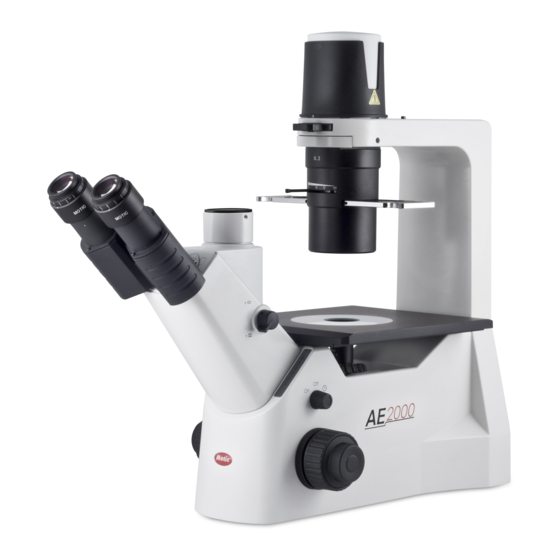
I. Nomenclature 1. Application AE2000 incorporates the Color Corrected Infinity Optical System (CCIS) that offers superior image quality for the transmitted and reflected illumination in the application of Living organism and tissue observation, Petri dish observation, Live cell in culture observation. - Page 6 Model AE2000...
- Page 7 Model AE2000 TRI Model AE2000 Ergo...
-
Page 8: Technical Data
3. Technical data Technical data AE2000 AE2000 TRI AE2000 Ergo Optical system Color-corrected infinity optics Total Magnification 40X - 400X 360° rotatable Siedentopf with upper and lower position: upper position offers approx. 40 mm extra viewing height Eyepiece tubes Interpupillary distance: 48 mm to 75 mm Binocular 45°... -
Page 9: Setting-Up The Instrument
II. Setting-up the Instrument 1. Working Environment The location should be free from dust, moisture, chemical vapours and from mechanical vibrations. Don't locate the instrument in bright or direct ambient light, in front of a lamp, or a will-lit bright wall. Best image will be achieved without significant ambient light. - Page 10 Attention: The plug of power adaptor is the "disconnect device" for whole unit. To save energy and environmental priciple, we recommend you to pull out the plug if you will not use the device in long time. This device complies with Part 15 of the FCC Rules. Operation is subject to the following two conditions: (1) this device may not cause harmful interference, and (2) this device must accept any interference received, including interference that may cause undesired operation.
-
Page 11: Assembling The Microscope Input Voltage
III. Assembling the Microscope 1. Installing the bulb In order to prevent electric shock always turn the power switch off (Fig.1) and unplug the power cord (Fig.2) before replacing the bulb. To remove lamphouse cover, press down lightly (1) and rotate counter clockwise (2). (Fig.3) Power Switch (Fig.1) Power Cord (Fig.2) Lamp house Cover (Fig.3) - Page 12 (Fig.7) (LED module) Firmly insert the LED module into the socket pinholes until it reaches the limit. This is Motic patent design to exchange LED module and halogen bulb on the same socket directly. After the LED module installation (Fig.6), secure it with the clamp screw by 1.5mm hexagonal screwdriver supplied with the microscope.
-
Page 13: Halogen Bulb
(Fig.8) 1.1 Halogen bulb The quartz halogen bulb, used as a light source, has higher luminance and colour temperature than conventional tungsten lamps. The luminance of halogen bulb is approximately four times brighter than the conventional tungsten lamps. As long as the lamp voltage is kept constant, the halogen lamp maintains the same level of brightness and colour temperature regardless of whether it is new or nearing the end of its life span. -
Page 14: Filter Holder
2. Filter Holder (Fig.9) (Fig.10) Filter holder is located under the lamphouse (Fig.9) for easy replacement of the filter. (Fig.10) 3. Mounting the Condenser Mount the condenser on the dovetail mount of the condenser holder (Fig.11) with the aperture diaphragm lever and index marks facing the front and secure it with the clamp screw by 2.5mm hexagonal screwdriver supplied with the microscope. -
Page 15: Installing The Objectives
3 kinds of Petri dish holder, 2 kinds of Heamacytometer holder and 96 well plates holder are available for your opinion. Secure the mechanical stage to the AE2000 plain stage using the two mounting screws (Fig.16) located beneath the stage on the right side (user facing the front of the instrument). -
Page 16: Mounting The Eyepieces
(Fig.16) The specimen can be moved to the desired position by turning the X-axis knob and Y-axis knob. 6. Mounting the Eyepieces Remove the dust caps from the eyepiece tubes. Use the same magnification eyepieces for both the eyes. Insert each eyepiece into the eyepiece sleeve, and tighten the clamp screws. -
Page 17: Microscopic Procedure
IV. Microscopic Procedure 1. Interpupillary Distance Adjustment Before adjusting the interpupillary distance, bring a specimen into focus using the 10x objective. Adjust the interpupillary distance so that both the right and left field of view become one. This adjustment will enable the user to observe the specimen with both eyes. 2. -
Page 18: Coarse And Fine Focusing
3.Coarse and fine focusing F ocusing function is realized with the coarse and fine focus knobs at the left and right of the microscope stand. The direction of vertical movement of the stage corresponds to the turning direction of the focus knobs. -
Page 19: Change The Illumination Between Halogen And Led
5. Change the illumination between Halogen and LED Attention: Unplug the plug-in power unit from the power outlet to protect user from electric shock and allow for a sufficient cool-down time of the6V 30W halogen lamp before you replace it. Press down lightly and rotate counter clockwise and remove lamphouse cover. -
Page 20: Brightfield Microscopy
6. Brightfield Microscopy Set the Phase annular diaphragm slider in the centre position without phase annular diaphragm. (Fig.24) Bring the specimen image into focus. The condenser aperture diaphragm is provided for adjusting the numerical aperture (N.A.) of the illuminating system of the microscope. It is important because it determines the resolution of the image, contrast, depth of focus and brightness. - Page 21 (Fig.25) If the objective phase plate and the annular of the slider do not coincide, use the two hexagonal screwdrivers (1.5mm) supplied with the microscope (Fig.26) to bring the slider annular ring to the centre of the phase plate (Fig.27), so that the image of the annular diaphragm is concentric with the phase plate image.
-
Page 22: Filter Selection
(Fig.28) (Fig.29) 8. Filter selection Filter holder could hold two pieces of filters Filter type Procedure ND (Neutral Density) filter For intensity adjustement in photomicrography For phase contrast and contrast adjustment with GIF (Green Interference) filter 546nm black and white film For general microscopy and colour Blue filter photomicrography... - Page 23 There is a auto power off switch locates above the left focusing knob. When “auto” is selected, the blue pilot lamp will be turned on. It indicates auto power off status. (Fig.30) If “auto” is selected, the light will automatically turn off after 15 minutes when no user in front of the unit.
-
Page 24: Photomicrographic Procedure (Model Ae2000 Trinocular)
V. Photomicrographic Procedure (Model AE2000 TRI) 1. Brightfield photomicrography The optical path selector knob (Fig.31) can be used to select the optical path to either the Binocular tube 100:0 or Binocular tube / vertical tube 20:80 (observation: photo). (Fig.31) Before starting photomicrography, check the following: ... -
Page 25: Troubleshooting Table
Aperture diaphragm closed too far Revolving nosepiece not clicked into position Optical path selector lever in intermediate position (Mod. AE2000 trinocular only) Aperture diaphragm closed too far Dust or dirt in field of view Dust or dirt on specimen’s surface... -
Page 26: Electrical
2. Electrical Problem Possible Cause Power supply not plugged in Lamp not installed Lamp does not light User left more than 15 minutes under auto mode Lamp burnt out Inadequate brightness Specified lamp not being used Lamp blows out immediately Specified lamp not being used Connectors are not securely connected Lamp flickers... -
Page 27: When Not In Use
CAUTION! Risk of danger. (See user manual) Proper handling of the microscope will ensure years of trouble free service. If repair become necessary, please contact your Motic agency or our Technical Service directly.
Need help?
Do you have a question about the AE2000 and is the answer not in the manual?
Questions and answers