Table of Contents
Advertisement
Advertisement
Table of Contents

Related Manuals for FAAC E145S


Summary of Contents for FAAC E145S
- Page 1 E145S...
- Page 2 Die Kunden dürfen nur für den Eigengebrauch Kopien anfertigen. Dieses Handbuch wurde 2020 veröffentlicht. © Copyright FAAC S.p.A. del 2020. Todos los derechos están reservados. No puede reproducirse, archivarse, distribuirse a terceros ni copiarse de ningún modo, ninguna parte de este manual, con medios mecánicos o mediante fotocopia, sin el permiso previo por escrito de FAAC S.p.A.
-
Page 3: Table Of Contents
6.2 Programming ........13 1 Technical data E145S....... . . 6 6.3 Operating logics . -
Page 4: Eu Declaration Of Conformity
E145S will be installed, prior to commissioning the machine. These activities include the analysis of all the risks associated with the machine and subsequent implementation of all safety measures intended to fulfil the essential safety requirements. -
Page 5: Meaning Of The Symbols Used
TABLE E.g.: 1 see Table 1. impact, crushing or shearing due to moving parts § CHAPTER/SECTION E.g.: §1.1 see section 1.1. LED off LED on LED flashing LED flashing quickly E145S 532369 - Rev.A... -
Page 6: Safety Recommendations
The work area must be kept tidy and must not be left unattended. Do not wear clothes or accessories (scarves, bracelets, etc.) that may get caught in moving parts. Always wear the personal protective equipment rec- E145S 532369 - Rev.A... -
Page 7: E145S
- It is prohibited to use and/or install accessories which have not been specifically authorised by FAAC S.p.A. - It is prohibited to use the E145S in the presence of faults which could compromise safety. - Do not allow water jets of any type or size to come into direct contact with the E145S. -
Page 8: Technical Specifications
3.5 TECHNICAL SPECIFICATIONS Technical data E145S 1 E145S It is an electronic board designed to control one Power supply voltage 90…260 V~ 50/60 Hz or two 230 V~ motors with an overall power of 800 Max power stand-by: 4 W W (800 W refers to the sum of the loads connected to sleep: <2 W... -
Page 9: Installation Requirements
The control accessories must be positioned in areas that are always accessible and not dangerous for the user. It is recommended to position the control acces- sories within the field of view of the automation. This E145S 532369 - Rev.A... -
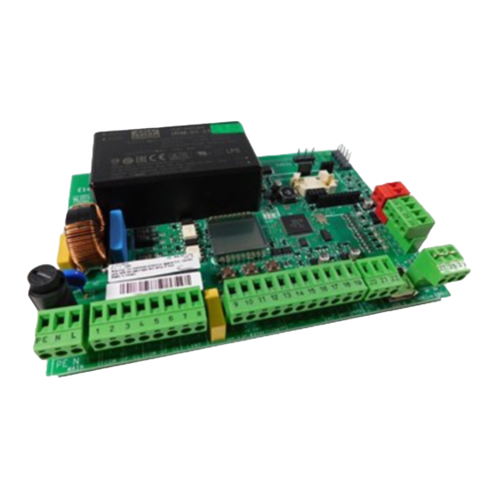
Page 10: Components
Inputs for sensitive edges Connector (5 pin) for FAAC radio/decoder boards FCC …FCA LEDs Inputs for opening/closing limit switches Connector (3 pin) for FAAC XF radio module USB LED USB pen drive present Removable terminal board for connecting limit switches... -
Page 11: Connections
• complete only for the leaf actuated by motor 1 in If the input is not used, bridge it with the two motor systems common contacts (-). Common contacts / Accessories power supply negative E145S 532369 - Rev.A... -
Page 12: Limit Switches
230V~ 60W max USB-A CONNECTIVITY 230V~ The E145S supplies 24 V " and is short-circuit pro- 13 14 15 16 17 18 19 20 21 22 27 28 29 tected with a maximum current of 500 mA for con- CR2032 LOCK nected accessories. -
Page 13: Electric Locks
IN1 IN2 IN3 IN4 IN5 230V~ 60W max The quick insertion connector J5 is specifically for FAAC The E145S can control up to two electric locks to block model XF radio modules. the leaves in the closed position. Insert as shown in the figure. -
Page 14: Motors
9 10 11 12 13 14 15 16 17 18 19 20 21 22 MAIN LAMP LOCK IN1 IN2 IN3 IN4 IN5 230V~ 60W max 230V~ Connect the Phase (L) and Neutral (N) to the 230 V~ E145S 532369 - Rev.A... -
Page 15: Set-Up
3 4 5 6 7 8 9 10 11 12 13 14 15 16 17 18 19 20 21 22 27 28 29 LAMP LOCK IN1 IN2 IN3 IN4 IN5 E145S 532369 - Rev.A... -
Page 16: Basic Programming Menu
The delay is applied to MOTOR 1. … (Adjustment step: 10 s) Displayed in seconds up to 59, then in steps of 10 s. NUMBER of MOTORS connected … (Adjustment step: 1 s) 1 motor … (Adjustment step: 10 s) 2 motors E145S 532369 - Rev.A... -
Page 17: Advanced Programming Menu
… (Adjustment step: 1%) SLOWDOWN LEAF 2 (NOT displayed if , or if Specifies the deceleration space for the leaf con- nected to MOTOR 2 (% of the total length of travel). … (Adjustment step: 1%) E145S 532369 - Rev.A... - Page 18 Timing of output OUT2 (with the same options … (Adjustment step: 1 s) MAINTENANCE REQUEST Enables/disables the maintenance alert when the programmed number of cycles has been reached as specified in the following functions ( disabled enabled E145S 532369 - Rev.A...
-
Page 19: Operating Logics
■ AUTOMATIC STEP BY STEP This logic only uses the OPEN command. OPEN if the automation is closed, causes it to open. The automation closes automatically after the pause time has elapsed. E145S 532369 - Rev.A... - Page 20 If an OPEN input is active at power up, it opens, otherwise it closes. OPEN during the pause, resets the pause time. OPEN during opening, is ignored. OPEN during closing, causes it to reopen. E145S 532369 - Rev.A...
-
Page 21: Setup
If the SETUP procedure doesn’t start or stops before it has been completed, the board exits from program- The limit switches in this application are indispen- ming mode and flashes on the display: check the sable. ERRORS that are present (Chapter § Diagnostics). E145S 532369 - Rev.A... -
Page 22: Configuring Movements And Timing
Encoder If encoders are installed, they must be that they correspond to the board installed / replaced. enabled to detect obstacles. Search for stop Reverse on obstacle via encoder is not active in the search for stop space. E145S 532369 - Rev.A... -
Page 23: Accessories
+24V +24V 1 pair of closing photocells and 1 pair of opening and 2 pairs of closing or opening photocells closing photocells IN4 o IN5 IN5 IN4 +24V +24V +24V +24V +24V +24V +24V +24V OP/CL E145S 532369 - Rev.A... -
Page 24: Sensitive Edges
If the sensitive edge is used to protect against a Limit switches hazard, it must comply with standard EN 12978. FCA1 The E145S board has two inputs for connecting sensi- FCC1 tive edges that are active during opening (EDGE1) or FCA2 during closing (EDGE2). -
Page 25: Bus 2Easy Devices
8.4 BUS 2EASY DEVICES than one pair of photocells with the same address, a It is possible to connect FAAC BUS 2easy devices (pho- conflict error is generated. tocells, sensitive edges, control devices) to this board. 2. Register the BUS 2easy photocells (see specific If no BUS 2easy accessories are used, leave connector section). -
Page 26: Bus 2Easy Encoder
3. Register the devices (see specific section). 4. Check the BUS 2easy devices(see specific section). 4 Correct connections MOT2 MOT1 MOT1 MOT2 DL2 on = encoder connected to MOT1 DL2 off = encoder connected to MOT2 5 E145S 532369 - Rev.A... -
Page 27: Bus 2Easy Control Devices
1 1 0 1 1 Open A_4 Open B_4 1 1 1 0 0 / 1 1 1 0 1 Open A_4 StopNC_2* 1 1 1 1 0 / 1 1 1 1 1 Open A_4 Close E145S 532369 - Rev.A... -
Page 28: Checking The Bus 2Easy Devices
8.5 XF RADIO MODULE CHECKING THE BUS 2EASY DEVICES 1. Select parameter in basic programming. If E145S is fitted with an OMNIDEC integrated two there are no devices registered, will appear channel decoding system that can memorise, via the XF radio module, FAAC radio controls that use the on the display, otherwise segment 13 will be lit. -
Page 29: Radio Controls - Rc/Lc
10 s. Use a LC/RC radio control that is already use by the automation, without having to use the board. 1. Take a radio control that is already in use and move close to the board. E145S 532369 - Rev.A... -
Page 30: Simply Connect
(SETUP and/or CONNECTIVITY modifications to operating parameters). CR2032 Simply Connect requires E145S firmware version FW 4.0 or later. When programming is taking place via Simply Connect, programming via the board is inhibited. 2EASY 1. -
Page 31: Upload/Download
9. UPLOAD/DOWNLOAD DOWNLOAD OPERATIONS There is a USB port on the E145S board that can be used for the following: Display Function File name - Load data from a USB pen drive (UPLOAD) Download board configuration E145.prg - saving data to a USB pen drive (DOWNLOAD). -
Page 32: Diagnostics
RADIO1 Channel 2 Omnidec (*) active not active RADIO2 not active Channel 2 Omnidec (*) active (*) Additional LED status or meanings are shown in the section on the accessory to which it refers. E145S 532369 - Rev.A... -
Page 33: Error Codes, Alarms, Info
Remove the cause of the SETUP in pro- SETUP is in progress. The notifica- short circuit. gress tion remains as long as the phase is in progress. Low energy con- E145S is operating on battery, in sumption mode SLEEP mode. E145S 532369 - Rev.A... - Page 34 A registration procedure is in pro- vice registration gress. in progress Programming in A registration procedure is in pro- progress gress via Simply Connect. Control board All data on the E145S has been data deletion deleted. E145S 532369 - Rev.A...
-
Page 35: Maintenance
11 lists the operations that should be performed N in industrial or commercial settings. on a regular basis on the E145S board in order to keep the automation working reliably and safely; Check that the sensitive edges operate correctly when an these are given purely as a guideline and should not obstacle is detected. -
Page 36: Cycle Counter
4. Exit and save the programming. 11.4 BUFFER BATTERY The batter y (model CR2032) is required if Simply Connectmodules are installed. It should be replaced with the power disconnected. Insert the batteries in the direction shown. E145S 532369 - Rev.A... - Page 37 FAAC S.p.A. Soc. Unipersonale Via Calari, 10 - 40069 Zola Predosa BOLOGNA - ITALY Tel. +39 051 61724 - Fax +39 051 09 57 820 www.faac.it - www.faacgroup.com E145S 532369 - Rev.A...
Need help?
Do you have a question about the E145S and is the answer not in the manual?
Questions and answers