Graco 226013 Instructions Manual
Topper units
Hide thumbs
Also See for 226013:
- Instructions-parts list manual (20 pages) ,
- Instructions manual (28 pages)
Table of Contents
Advertisement
Quick Links
Instructions
Topper Units
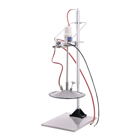
Grease dispense unit with pneumatic pump elevator for easy drum replacement. For
professional use only.
Model 226013
®
50:1 Ratio Fire-Ball
Pump
5000 psi (34.5 MPa, 345 bar) Maximum Working Pres-
sure
100 PSI (0.68 MPa, 6.89 bar) Maximum Air Pressure
Model 226018
®
50:1 Ratio President
Pump
4000 psi (27.6 MPa, 276 bar) Maximum Working
Pressure
80 PSI (0.55 MPa, 5.5 bar) Maximum Air Pressure
Model 244637
®
75:1 Ratio President
Pump
4000 psi (27.6 MPa, 276 bar) Maximum Working
Pressure
80 PSI (0.55 MPa, 5.5 bar) Maximum Air Pressure
Model 204490, Elevator and Inductor
without pump or hose kit
Important Safety Instructions
Read all warnings and instructions in this
manual. Save these instructions.
306556S
EN
Advertisement
Table of Contents

Related Manuals for Graco 226013


Summary of Contents for Graco 226013
- Page 1 Instructions Topper Units 306556S Grease dispense unit with pneumatic pump elevator for easy drum replacement. For professional use only. Model 226013 Model 244637 ® ® 50:1 Ratio Fire-Ball Pump 75:1 Ratio President Pump 5000 psi (34.5 MPa, 345 bar) Maximum Working Pres- 4000 psi (27.6 MPa, 276 bar) Maximum Working...
-
Page 2: Table Of Contents
Technical Data ......19 Graco Standard Warranty ....20... -
Page 3: Warnings
Warnings Warnings The following warnings are for the setup, use, grounding, maintenance, and repair of this equipment. The exclama- tion point symbol alerts you to a general warning and the hazard symbols refer to procedure-specific risks. When these symbols appear in the body of this manual or on warning labels, refer back to these Warnings. Product-specific hazard symbols and warnings not covered in this section may appear throughout the body of this manual where applicable. - Page 4 Warnings WARNING TOXIC FLUID HAZARD Hazardous fluid or toxic fumes can cause serious injury or death if splashed in the eyes or on the skin, inhaled, or swallowed. • Know the specific hazards of the fluid you are using. • Store hazardous fluid in an approved container.
-
Page 5: Installation
Installation Installation Grounding 3. Connect the other end of the ground wire to a true earth ground. (Fig 1). The equipment must be grounded to reduce the risk of static sparking and electric shock. Electric or static sparking can cause fumes to ignite or explode. Improper grounding can cause electric shock. -
Page 6: Typical Installation
4. Place the inductor plate (2, 18, or 22) on the mount- for selecting and installing this system. It is not an actual ing base (102). system design. Contact your local Graco representative for assistance in designing a system to suit your particu- lar needs. - Page 7 Installation Mounting the Pump 5. Tighten the lock nut (11 or 24) securely. Continue with Step 4 below. Models 226013, 226018, 244637 DETAIL 1. Mount the pump support bracket (86). (F . 4) pump riser 8 or 23 tube 11 or 24...
- Page 8 Installation All Models 4. Connect one end of the 36 in. (914 mm) hose into the adapter and the other hose end into the Refer to F . 7 for the following Steps. snap-over valve’s (27) union (82). (F . 8) 4.
- Page 9 Installation 8. Install a bleed-type master air valve on the pump’s air supply line. 9. Install a fluid shutoff valve on the fluid supply line to shut off fluid to the pump. 10. Finish assembling the hoses and fittings as shown on Parts Drawing Page 16.
-
Page 10: Operation
(73). 12. Close the inductor plate vent by turning the knob (10) clockwise. 13. For Models 226013, 226018, and 244637 only: a. Open the bleeder valve (94) at the pump outlet by turning the thumbscrew counter clockwise. -
Page 11: Removing A Drum
Operation Removing a Drum 1. Relive pressure, see Pressure Relief Procedure, page 5. 2. Press in and hold the air-assist valve (47) until the inductor plate rises above the drum. Release the valve. (F . 9) 3. Open the snap-over valve (27) and raise the eleva- tor to full height. -
Page 12: Maintenance
(41). For Model 204490: Loosen the inductor plate set screws (19). For Models 226013, 226018, and 244637: Unscrew the locking nut (11 or 24), taking note of the number of turns needed. 3. Push the snap-over valve (27) to lower the pump. -
Page 13: Troubleshooting
Troubleshooting Troubleshooting Problem Cause Solution 1. Open inductor plate vent 1. Close the inductor plate. 2. Loose inductor plate sleeve lock- 2. Tighten the locking nuts. Low flow or air sucked into pump or ing nut under inductor plate. 3. Replace seals; See Parts Draw- 3. -
Page 14: Parts
205102 HOSE KIT See parts below See parts on page 18 101 205339 ELEVATOR BASE Model 226013 See parts below Pump, Elevator, and Inductor Plate Assembly 107 239730 75:1 RATIO PRESIDENT PUMP Includes items 1, 25, 89, 90, 91 and 101 See manual 308777 for parts Ref No. - Page 15 Parts Ref No. 1: Part No. 204353 Inductor Plate Assembly: 400 lb Drum size Fits 50:1 Fire-Ball In-Line Pump; Includes items 2-16 Ref No.Part No. Description Qty. 204502 PLATE, inductor, bare 100015 NUT, hex, mscr, 1/4-20 UNC-2a Tapered 100021 CAPSCREW, hex hd, 1/4-20 UNC-2a x 1” shoulder 104663 PLUG, pipe, 3/4 npt (f)
- Page 16 Parts Ref. No. 27 Ref. No. 42 29 36 Snap-Over Valve Assembly Restrictor Valve Assembly Includes items 28 to 40 Includes items 43 to 46 1/8 npt 0729 0730 0732B 66 74 Ref. No. 47 Air Assist Valve Assembly Includes items 48 to 60 3/8 npt 1/4 npt 0731...
- Page 17 Parts Ref No. 25: Part No. 204461 Wishbone Support Assembly Part No. Description Qty. Part No. Description Qty. 204560 HOSE, air, cpld 3/8 npt (m) 3/8” 202295 SNAP-OVER VALVE ASSEMBLY (9.6mm) ID, 18” (457 mm) long Includes items 28 - 40 204561 HOSE, air, cpld 3/8 npt (m) 3/8”...
- Page 18 Parts Ref No. 91: Part No. 204467 Ref No. 97: Part No. 205102 Fire-Ball Delivery Hose Kit President Delivery Hose Kit Includes items 92 - 94, 96, and 115 Includes items 94, 96, 98, 99, and 110 Part No. Description Qty.
-
Page 19: Technical Data
50:1 Ratio President Pump 80 psi 0.6 MPa, 6 bar 75:1 Ratio President Pump 0.6 MPa, 6 bar 80 psi Weight Model 226013 122 lb 55 kg 50:1 Ratio Fire-Ball Pump Model 226018 136 lb 61 kg 50:1 Ratio President Pump... -
Page 20: Graco Standard Warranty
With the exception of any special, extended, or limited warranty published by Graco, Graco will, for a period of twelve months from the date of sale, repair or replace any part of the equipment determined by Graco to be defective.
Need help?
Do you have a question about the 226013 and is the answer not in the manual?
Questions and answers