Table of Contents

Related Manuals for PKP DB51


Summary of Contents for PKP DB51
- Page 1 Instruction Manual DB51 Compact mass thermal flowmeter and counter for gases PKP Prozessmesstechnik GmbH Borsigstraße 24 D-65205 Wiesbaden-Nordenstadt Tel.: ++49-(0)6122-7055-0 Fax: ++49-(0)6122-7055-50 Email: info@pkp.de www.pkp.de...
-
Page 2: Foreword
Foreword Dear customer, thank you very much for deciding in favour of the DB51. Please read this installation and operation manual carefully before mounting and initiating the device and follow our advice. A riskless operation and a correct functioning of the... -
Page 3: Table Of Contents
Scaling Analogue output Compressed Air ............... 8 Installation Description ....................9 Pipe/tube requirements ......................9 Inlet / outlet runs ........................9 Installation of DB51......................10 Display head Position ......................10 Flow measuring ranges ....................11 Flow for different gases....................... 11 Dimensions ........................12 With measurement section and screw-in thread .............. - Page 4 11.3.4.2 Language ........................30 11.3.4.3 Display / Touch ......................31 11.3.5 Advanced ......................... 31 11.3.6 4 -20mA ........................... 32 DB51 Info ........................34 11.3.7 11.4 MBus............................35 11.4.1 Default Settings communication ..................35 11.4.2 Default values transmitted ....................35 Status / Error messages ...................36 12.1...
-
Page 5: Intended Use
We are also not liable for consequential damage resulting from the delivery, capability or use of this device. We offer you to take back the instruments of the instruments family DB51 which you would like to dispose of. -
Page 6: Instruments Description
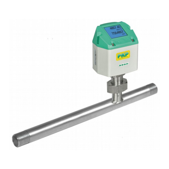
Instruments decription 3 Instruments description The DB51 is a compact consumption counter for compressed air and gases. Special features: - Optimum accuracy due to compact design - Integrated Display showing Flow, consumption, velocity and temperature - Input inner tube diameter via display keys - Units free selectable. -
Page 7: Technical Data
Version with flange DIN EN 1092-1: Stainless steel 1.4404 Protection class: IP65 * m.v. = measured values f.s. = full scale Scope of delivery 1x Flow sensor DB51 with measuring section 1x Calibration certificate 1x Instruction manual DB51 English V1.22 Page 7 of 40... -
Page 8: Scaling Analogue Output Compressed Air
Reference DIN1945/ ISO 1217: 20°C, 1000 mbar (Reference during calibration) Description Version Analogue output Low Speed 0...25 l/min Standard 0...50 l/min DB51 with integrated 1/4" meas. section 4… 20 mA = 0...105 l/min High Speed 0...130 l/min Low Speed 0...20 m³/h Standard 0...45 m³/h... -
Page 9: Installation Description
Attention: The dimensions of the DB51 consumption counter measuring sections do not fullfill the required minimum lengths of the input and outlet runs. Please ensure recommended in - and outlet distances, dimensions for measuring sections see page 12 and 13. -
Page 10: Installation Of Db51
Installation Installation of DB51 The sensor DB51 is pre-supplied with the measuring section. • An installation at customer site is only allowed in the unpressurized state of the system • It has to be checked whether the VA520 is correctly installed in the measuring section, the flow direction arrows must point in the same direction. -
Page 11: Flow Measuring Ranges
DVGW admission, however, it can be used for measurements in natural gas. A DVGW admission is not mandatory. The area outside the pipeline (ambient area of the sensor) must not be an explosive area. DB51 English V1.22 Page 11 of 40... -
Page 12: Dimensions
26,9 / 21,7 179,8 166,3 DB51 1“ R 1“ DN 25 33,7 / 27,3 183,2 166,3 DB51 1 1/4" DN 32 42,4 / 36,0 187,5 166,3 R 1 1/4" DB51 1 1/2“ R 1 1/2“ DN 40 48,3 / 41,9... -
Page 13: With Measurement Section And Flange (Material Stainless Steel 1.4404)
218,8 166,3 4 x 14 DB51 1“ DN 25 33,7 / 27,3 223,8 166,3 4 x 14 DB51 1 1/4" DN 32 42,4 / 36,0 263,3 166,3 4 x 18 DB51 1 1/2“ DN 40 48,3 / 41,9 2 40,7... -
Page 14: Electrical Wiring
DIP Switch to “On”. It must be ensured that the connection plugs are still plugged and the gasket is installed correctly, see also chapter 4.1. Alternatively, a 120R resistor can be installed in the plug between pin 2 and pin DB51 English V1.22 Page 14 of 40... -
Page 15: Ethernet (Optional Poe)
Data LINES: 1,2 und 3,4 PoE LINES: 5,6 und 7,8 M12 x 1 Connection cable: Cat 6. Shield connected Remark: VA520 Power Classification acc. IEEE 802.3af: Class 2 (3,84W – 6,49W) *PoE: Power over Ethernet DB51 EN V1.22 Page 15 o 40... -
Page 16: Operation
Only for version with display “OK“ ( ) “Up“ ( ↵ The operation of the DB51 is done by the two capacitive key buttons Up ( ) and Enter ( DB51 English V1.22 Page 16 of 40... -
Page 17: Initialization
Operation 11.1 Initialization After switching on the DB51, the initialized screen is displayed followed by the main menu. 11.2 Main menu Gas / Status Info HW Version Modbus ID Page-No. SW Version „ “ Switching to pages 2-5 or back by pressing key 410,34 391.23... -
Page 18: Settings
For changes, first select the menu item „ “ with key and then confirm it with “OK“. 11.3.1.1 Input / change tube diameter For DB51 not adjustable (suspended) as voted on included measuring section with corresponding pipe diameter. DB51 EN V1.22 Page 18 o 40... -
Page 19: Input / Change Consumption Counter
In case the quantity of units selectable are not presentable on one page, pleas move to next „<<“ page by pressing Confirm selection by pressing 2x „OK“. Procedure for all 4 measurement variables is analogous. DB51 EN V1.22 Page 19 o 40... -
Page 20: Definition Of The Reference Conditions
1. Complete with "OK" activate next number position. Procedure for changing the reference temperature is the same. DB51 EN V1.22 Page 20 o 40 Under point "Filtertime" together with the appropriate "Filter Grade" an attenuation can... - Page 21 Setup → Sensor Setup→ Advanced → AV-Time The time period for averaging can be entered here. Input values of -1440 1 [minutes] are possible. For average values see display window 3 + 4 DB51 EN V1.22 Page 21 o 40...
-
Page 22: Setting Of Zero Point And Low-Flow Cut Off
Setup → Sensor Setup → ZP Adjust t → Reset „Reset“ By selection of all settings for „ZeroPnt“ and. „CutOff“ are reset. 1,03 „“ Menu item to be select with button „OK“ confirm the reset with „Back“ Leave menu with button DB51 EN V1.22 Page 22 o 40... -
Page 23: Modbus Settings
Operation 11.3.2 Modbus settings 11.3.2.1 Modbus RTU Setup The Flow sensors DB51 comes with a Modbus RTU Interface. Before commissioning the sensor the communication parameters • Modbus ID, Baudrate, Parity und Stop bit must be set in order to ensure the communication with the Modbus master. -
Page 24: Modbus Tcp (Optional)
Operation 11.3.2.2 Modbus TCP (Optional) The Flow sensors DB51 comes optional with a Modbus TCP Interface (HW Interface: M12 x 1 X-coded connector). Device supports with this option the Modbus TCP protocol for communication with SCADA systems. TCP port is set to 502 by default. Port can be changed at the sensor. -
Page 25: Network Settings Static Ip
"OK" key. Change the values with the ">" key, and accept the values with the "OK" key. Procedure for "Subnet" "Gateway" analogous. „Save“ Store the settings by DB51 EN V1.22 Page 25 o 40... -
Page 26: Modbus Tcp Settings
(Little Endian) and "CDAB" (Middle Endian) Saving the changes by pressing "Save", „>“ therefore select it with key and then confirm it with "OK". Reset to the default settings by activating "Set to Default"- DB51 EN V1.22 Page 26 o 40... -
Page 27: Modbus Settings (2001
1181 1180 Float Flow in Ncfm 1189 1188 Float Flow in kg/h 1197 1196 Float 1205 1204 Float Flow in kg/min 1213 1212 Float Flow in kg/s 1221 1220 Float Flow in kW DB51 EN V1.22 Page 27 o 40... - Page 28 Remark: • For DS400 / DS 500 / Handheld devices - Modbus Sensor Datatype „ Data Type R4-32“ match with „Data Type Float“ • For more additional Modbus values please refer to VA5xx_Modbus_RTU_Slave_Installation_1.09_EN.doc DB51 EN V1.22 Page 28 o 40...
-
Page 29: Pulse /Alarm
3000 3000000 Table 1 Maximum flow for pulse output Entering pulse values that are not allow a presentation to the full scale value, are not allowed. Entries are discarded and error message displayed. DB51 EN V1.22 Page 29 o 40... -
Page 30: User Setup
11.3.4.2 Language → → Settings UserSetup Language Currently 4 languages have been implemented „“ and could be selected with button Change of language by confirming with “OK”. “back”. Leaving the menu with button DB51 EN V1.22 Page 30 o 40... -
Page 31: Display / Touch
10s. To do this, use the "OK" button to enter the operating menu during this period 11.3.5 Advanced Settings→ Advanced „Factory Reset“ By pressing the sensor is set back to the factory settings. DB51 EN V1.22 Page 31 o 40... -
Page 32: -20Ma
„OK“ and confirm selection by pressing → Settings → 4-20mA Channel 1 The 4-20 mA Analogue output of the Sensor DB51 can be individually adjusted. It is possible to assign following values „Temperature“, „Velocity“ und „Flow“ to the channel CH 1. - Page 33 To make changes first select a menu item "Current Error" „“ „OK“ with button and then select by pressing the the desired mode „Save“ For saving the changes done press button “Cancel”. discard the changes press button Leaving the menu with „Back“. DB51 EN V1.22 Page 33 o 40...
-
Page 34: Db51 Info
Operation 11.3.7 DB51 Info → Settings Info Here you get a brief description of the sensor data incl. the calibration data. 92,7 m/s 600m³/h Under Details, you are able to see in addition the calibration conditions. Run Time: 2d 21h 23m 12s... -
Page 35: Mbus
11.4.2 Default values transmitted Value 1 with [Unit]*: Consumption [m³] Value 2 with [Unit]*: Flow [m³/h] Consumption [m³] Value 3 with [Unit]*: Gas temperature [°C] *All Values could be changed / preset in production DB51 EN V1.22 Page 35 o 40... -
Page 36: Status / Error Messages
12.1 Status messages • On the part of PKP Prozessmesstechnik GmbH a regular re-calibration is recommended, see chapter 13. At delivery, the date at which the next recalibration is recommended is internally entered. When this date is reached, a message appears in the display with the status message „CAL“. -
Page 37: Error Messages
For sensors with a galvanically isolated 4-20mA output, a min. Supply voltage of 17.5V is required. If this value is undershot, the error message „Low Voltage 4-20mA“ is displayed. Error messages: *** DB51 *** *** DB51 *** Low Voltage Heater Error... -
Page 38: Maintenance
The warranty time for the DB51 is 12 months. If no other definitions are given the accessory parts have a warranty time of 6 months. Warranty services do not extend the warranty time. - Page 39 • zero balance possible at instrument Description: Typical applications: Model DB51 thermal mass flow meters and counters report Series DB51 thermal mass flow meters and counters provide and measure mass flow rates and totals of non-aggressive flow measurement of non-aggressive gases in ¼" to 1 ½"...
- Page 40 4...20 mA scaling reference conditions (°C, mbar) pulse value Zero point balance leak flow volume suppression Indication: Rotatable at 180° PKP Prozessmesstechnik GmbH +49 (0) 6122-7055-0 • T +49 (0) 6122 7055-50 Borsigstr. 24 • D-65205 Wiesbaden info@pkp.de • www.pkp.de...
- Page 41 275,7 175,7 *Attention: Shortened inlet section! Please observe the recommended minimum inlet section (length = 10 m inner diameter) on site! PKP Prozessmesstechnik GmbH +49 (0) 6122-7055-0 • T +49 (0) 6122 7055-50 Borsigstr. 24 • D-65205 Wiesbaden info@pkp.de •...
- Page 42 5= 5-pole DB51-Z.V1: Cover lid for flow conditioner pipe, aluminium Cable length: DB51-Z.V2: Cover lid for flow conditioner pipe, st.st. 1.4404 0 = without cable for self assembly 2 = 2 m PVC cable (standard) DB50-Z.K5: Factory calibration, 5 points...
Need help?
Do you have a question about the DB51 and is the answer not in the manual?
Questions and answers