Table of Contents
Advertisement
Quick Links
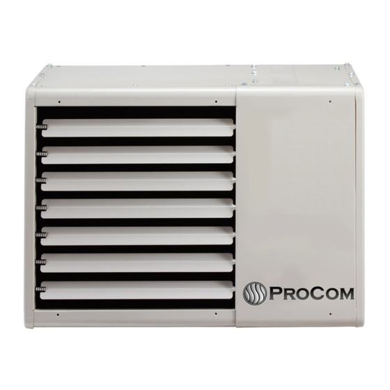
VENTED GARAGE HEATER
Model #GHBVN50, GHBVN80
GHBVL50, GHBVL80
PFS
C
WARNING: IF THE INFORMATION IN THIS MANUAL IS NOT FOLLOWED
EXACTLY, A FIRE OR EXPLOSION MAY RESULT CAUSING PROPERTY
DAMAGE, PERSONAL INJURY, OR LOSS OF LIFE.
– Do not store or use gasoline or other flammable vapors and liquids in vicinity of
this or any other appliance.
WHAT TO DO IF YOU SMELL GAS
•
Do not try to light any appliance.
•
Do not touch any electrical switch; do not use any phone in your building.
•
Immediately call your gas supplier from a neighbor's phone. Follow the gas
supplier's instructions.
•
If you cannot reach your gas supplier, call the fire department.
– Installation and service must be performed by a qualified installer, service agency
or the gas supplier.
INSTALLER: Leave this manual with the appliance. CONSUMER: Retain this manual
for future reference.
WARNING: Improper installation, adjustment, alteration, service or maintenance
can cause injury or property damage. Refer to this manual for correct installation and
operational procedures. For assistance or additional information consult a qualified
installer, service agency or the gas supplier.
Questions about installation, operation, or troubleshooting? Before returning to your retailer, contact our
customer service department at 1-877-886-5989, 8:00 a.m.- 4:30p.m., EST, Monday-Friday or e-mail
customerservice@usaprocom.com.
®
US
CAUTION - FOR YOUR SAFETY
GHBV48/78651
Advertisement
Table of Contents

Subscribe to Our Youtube Channel
Related Manuals for Procom GHBVN50


Summary of Contents for Procom GHBVN50
- Page 1 VENTED GARAGE HEATER Model #GHBVN50, GHBVN80 GHBVL50, GHBVL80 ® CAUTION - FOR YOUR SAFETY WARNING: IF THE INFORMATION IN THIS MANUAL IS NOT FOLLOWED EXACTLY, A FIRE OR EXPLOSION MAY RESULT CAUSING PROPERTY DAMAGE, PERSONAL INJURY, OR LOSS OF LIFE.
-
Page 2: Table Of Contents
TABLE OF CONTENTS Important Safety Information................................3 Unpacking......................................3 ANSI Requirement in USA..................................4 CSA Requirement in Canada................................4 Pre-Installation Preparation...................................5 Installation ......................................5 Operation......................................16 Care & Maintenance...................................18 Replacement Parts.....................................19 WARNING: Read the installation & operation instructions before using this appliance. IMPORTANT: Read instructions and warnings carefully before starting installation. Failure to follow these instructions may result in a possible fire hazard and will void the warranty. -
Page 3: Important Safety Information
IMPORTANT SAFETY INFORMATION IMPORTANT: Read this owner’s manual carefully and completely before trying to assemble, operate, or service this heater. Improper use of this heater can cause serious injury or death from burns, fire, explosion, electrical shock, and carbon monoxide poisoning. WARNING: Do not store or use gasoline or other flammable vapors or liquids in the vicinity of this or any other appliance. -
Page 4: Ansi Requirement In Usa
ANSI REQUIREMENTS IN USA Installation of gas unit heaters must conform with local building codes or, in the absence of local codes, with the current ANSI Z223.1, National Fuel Gas Code. Installation in parking structures must be in accordance with the current ANSI/NFPA No. 88A, Standard for Parking Structures. -
Page 5: Pre-Installation Preparation
PRE-INSTALLATION PREPARATION GARAGE INSTALLATIONS 1. In a storage area, clearance from heaters to combustible materials must be such that the material shall not attain a temperature above 160°F by continuous operation of the unit. 2. Maintain an 8 foot (2m) minimum clearance from the floor to the bottom of the heater. Refer to the current edition of CSA−B149 for installation compliance codes. - Page 6 GENERAL RECOMMENDATIONS AND REQUIREMENTS NOTE: The vent is a passageway, vertical or nearly so, used to convey flue gases from an appliance, or its vent connector, to the outside atmosphere. The vent connector is the pipe or duct that connects a fuel−gas burning appliance to a vent or chimney.
- Page 7 7. The vent connector shall be supported without any dips or sags. Vertical vents shall be supported in accordance with their listing and manufacturers’ instructions. All horizontal vent connector runs shall have a slope up to the vertical vent of at least 1/4" per foot (1mm per 50mm). 8.
- Page 8 HORIZONTAL VENTING – COMMERCIAL 1. Horizontal commercial installations are for buildings which are not attached to living spaces. The vent may be single wall vent material installed according to the sections General Recommendations and Requirements and Horizontal Venting – General and Horizontal Venting − Commercial. See figures 4, 5, and 6. 2.
- Page 9 Fig.6 HORIZONTAL VENTING−RESIDENTIAL 1. For horizontal residential installations these units are certified as Category I appliances. The vent may be single wall material minimum 25 gauge galvanized steel or equivalent grade stainless steel or a single section of type B−1 vent installed according to the sections General Recommendations and Requirements and Horizontal Venting General and Horizontal Venting −...
- Page 10 VENTING USING A MASONRY CHIMNEY The following additional requirements apply when a lined masonry chimney is being used to vent the compact unit heater. IMPORTANT: Single appliance venting of a fan assisted unit heater into a tile lined masonry chimney (interior or outside wall) is prohibited.
- Page 11 Electrical Connections...
- Page 12 WALL THERMOSTAT INSTALLATION INSTRUCTIONS PREPARATION BEFORE INSTALLATION 1. Remove the wall thermostat from package. 2. Confirm the garage heater is installed and control is in the "off" position. 3. Select location to install the wall thermostat. Prepare three 20~22AWG wires (not supplied) by cutting to the length that is needed for your particular installation.
- Page 13 3. Install the wall thermostat using screws included with your heater and screw into a wall stud. If unable to screw into a wall stud, screw anchors should be used. Do not allow wires to touch each other or parts of thermostat .Wires must be routed through the hole in the back plate, below the terminal block.
- Page 14 CAUTION: Use only new black iron or steel pipe. Internally tinned copper tubing may be used in certain areas. Check your local codes. Use pipe of ½ inch diameter or greater to allow proper volume gas to heater. If pipe is too small, loss of pressure will occur.
- Page 15 CHECKING GAS CONNECTIONS WARNING: Test all gas piping and connections for leaks after installing or servicing. Correct all leaks immediately. WARNING: Never use an open flame to check for a leak. Apply a mixture of liquid soap and water to all joints. If bubbles form, there may be a leak.
-
Page 16: Operation
OPERATION FOR YOUR SAFETY READ BEFORE LIGHTING WARNING: If you do not follow these instructions exactly, a fire or explosion may result causing property damage, personal injury, or loss of life. • If you cannot reach your gas supplier, call the fire A. - Page 17 Ignition Control LED The ignition control board contains a green LED which indicates the following: TABLE 3 IGNITION CONTROL LED UNIT OPERATION Slow. Flash* Normal Operation − No call for heat Fast Flash Normal Operation − Call for heat 2 Flashes System lockout −...
-
Page 18: Care & Maintenance
A natural to LP/propane gas changeover kit is required to convert unit. Refer to the installation instructions supplied with the changeover kit for conversion procedure. If unit is installed at an altitude greater than 7500 feet (1372m), unit must be derated by four percent for each additional 1000 feet (305m) above 7500 feet or as specified by local authority having jurisdiction. -
Page 19: Replacement Parts
COMBUSTION AIR INDUCER Under normal operating conditions, the combustion air inducer should be checked and cleaned prior to the heating season with the power supply disconnected. Use a small brush to clean inducer wheel. ELECTRICAL 1. Check all wiring for loose connections. 2. - Page 20 REPLACEMENT PARTS LIST This list contains replaceable parts for your heater. When ordering replacement parts, follow the instructions listed under Replacement Parts on page 19 of this manual. Key No. Description Part# GHBVN50 GHBVN80 CIRCUIT BOARD PG01-1M PG01-1M KSD301-112 LIMIT SENSOR...
- Page 21 ILLUSTRATED PARTS GHBVN50 GHBVN80...
- Page 22 WARRANTY INFORMATION Keep This Warranty IMPORTANT: We urge you to fill your warranty registration card within TEN(10) days of date of installation, complete with the entire serial number which can be found on the rating plate. Retain this portion of the card for your record. Always specify model and serial numbers when communicating with customer service.
Need help?
Do you have a question about the GHBVN50 and is the answer not in the manual?
Questions and answers