Table of Contents
Advertisement
VENT - FREE GAS LOG HEATER
WARNING: If the information in this manual is not
followed exactly, a fire or explosion may result causing
property damage, personal injury or loss of life.
— Do not store or use gasoline or other flammable va-
pors and liquids in the vicinity of this or any other
appliance.
— WHAT TO DO IF YOU SMELL GAS
• Do not try to light any appliance.
• Do not touch any electrical switch; do not use any
phone in your building.
• Immediately call your gas supplier from a neighbor's
phone. Follow the gas supplier's instructions.
• If you cannot reach your gas supplier, call the fire
department.
— Installation and service must be performed by a quali-
fied installer, service agency or the gas supplier.
WARNING: This appliance is equipped for natural and
propane gas. Field conversion is not permitted other than
between natural or propane gases.
Questions, problems, missing parts? Before returning to your retailer, call
our customer service department at 1-866-573-0674, 8:00 am - 4:30 pm CST,
MODEL PCNSDS24RT
Monday through Friday or email contact@usaprocom.com
PFS
®
US
Advertisement
Table of Contents

Related Manuals for Procom PCNSDS24RT


Summary of Contents for Procom PCNSDS24RT
- Page 1 VENT - FREE GAS LOG HEATER MODEL PCNSDS24RT ® WARNING: If the information in this manual is not followed exactly, a fire or explosion may result causing property damage, personal injury or loss of life. — Do not store or use gasoline or other flammable va- pors and liquids in the vicinity of this or any other appliance.
-
Page 2: Table Of Contents
* Aftermarket: Completion of sale, not for purpose of resale, from the manufacturer. PROCOM HEATING, INC. PATENT INFORMATION This product may be covered by one or more of the following United States patents:... -
Page 3: Specifications
SPECIFICATIONS MODEL PCNSDS24RT Ignition Electronic Piezo Gas Type Natural Propane Input Rating 34,000 BTU/Hr 34,000 BTU/Hr Manifold Pressure 4" W.C. 9" W.C. Inlet Gas Pressure* Max. 9" W.C. Max. 14" W.C. (inches of water) Min. 5" W.C. Min. 11" W.C. - Page 4 SAFETY WARNING: Make sure a fire- WARNING: FIRE, EXPLOSION place screen is in place before AND ASPHYXIATION HAZARD running heater. Improper adjustment, altera- tion, service, maintenance, or 1. Do not place propane supply tank(s) in- installation of this heater or its side any structure.
-
Page 5: Product Features
SAFETY 13. Do not use this heater if any log is broken. service technician to inspect the room Do not operate heater if a log is chipped heater and to replace any part of the (dime-size or larger). control system and any gas control which 14. -
Page 6: Water Vapor: A By-Product Of Unvented Room Heaters
UNPACKING Burner CAUTION: Do not remove the data plates from the burner Pilot pan. The data plates contain important product information. 1. Remove logs and burner base assembly from carton. NOTE: Do not pick up burner base assembly by burners as this could damage heater. - Page 7 AIR FOR COMBUSTION AND VENTILATION WARNING: This heater shall not be installed in a room 12" or space unless the required Ventilation volume of indoor combustion Ventilation Grills Grills Into Into Adjoining Room, Adjoining air is provided by the method Option 2 Remove Room,...
-
Page 8: Installation
INSTALLATION NOTICE: This heater is intended WARNING: Never install the for use as supplemental heat. heater Use this heater along with your • in a bedroom or bathroom primary heating system. Do not • in a recreational vehicle install this heater as your pri- •... - Page 9 INSTALLATION IMPORTANT: Vent-free heaters add moisture to the air. Although this is beneficial, installing heater in rooms without enough ventilation air may cause mildew to form too much moisture. See Air for Combustion and Ventilation, pages 6 and 7. Before beginning assembly or operation of the product, make sure all parts are pres- ent.
- Page 10 INSTALLATION you must have noncombustible material be- NOTICE: This heater may be hind it. Noncombustible material must extend used as a vented product. If so, at least 8" up. If noncombustible material is you must always operate log set less than 12", you must install the fireplace hood accessory.
- Page 11 INSTALLATION FLOOR CLEARANCES A. If installing appliance on the floor level, B. If combustible materials are less than 14" you must maintain the minimum distance to the fireplace, you must install appliance of 14" to combustibles (see Figure 8). at least 5" above the combustible flooring (see Figure 9).
- Page 12 INSTALLATION GAS SELECTION Yellow Natural Gas Blue Propane Gas This appliance is factory Plunger Underneath Plunger DO NOT preset for propane gas. No Metal Cap REMOVE! changes are required for connecting to propane. Only a qualified installer or service techni- cian can perform gas selection and connecting to gas supply.
- Page 13 INSTALLATION FOR NATURAL GAS Fitting INSTALLATION: YELLOW supplied by installer, 1. Remove the metal cap installed over the may vary. NG regulator inlet. Metal Cap 2. Install metal cap over propane regulator inlet. This will keep debris out of regulator. Use only the metal cap.
- Page 14 INSTALLATION INSTALLING HEATER BASE ASSEMBLY 2. Mark screw locations through holes in WARNING: You must secure mounting brackets (see Figure 12). If this heater to fireplace floor. If installing in a brick-bottom fireplace, mark not, heater will move when you screw locations in mortar joint of bricks.
- Page 15 INSTALLATION CONNECTING TO GAS SUPPLY WARNING: A qualified ser- CAUTION: For natural gas, vice technician must connect check your gas line pressure heater to gas supply. Follow all before connecting heater to gas local codes. line. Gas line pressure must be no greater than 9.5"...
- Page 16 INSTALLATION Typical Inlet Pipe Diameters Install sediment trap in supply line as shown Use 1/2" black iron pipe or greater. Installa- in Figure 14. Place sediment trap where it is tion must include an equipment shutoff valve, within reach for cleaning. Place sediment trap union, and plugged 1/8"...
- Page 17 INSTALLATION CHECKING GAS CONNECTIONS 3. Check all joints from gas meter to equip- WARNING: Test all gas piping ment shutoff valve for natural gas or pro- and connections, internal and pane supply to equipment shutoff valve external to unit, for leaks after for propane (see Figure 17 or 18).
- Page 18 INSTALLATION INSTALLING BATTERIES Ignitor CAUTION: Do not mix old and Unscrew ignitor cap and install a AAA battery with the + pointing out. Replace cap. new batteries. Do not mix alka- line, standard (carbon - zinc), or rechargeable (nickel - cadmium) batteries.
- Page 19 INSTALLING REMOTE RECEIVER 1. Locate red and black wires from solenoid 2. Place receiver to the side of the log set, valve on right side of heater. Connect (see Figure 21). wires to receiver, red to red, black to black, (see Figure 21).
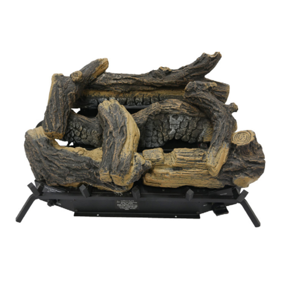
- Page 20 INSTALLATION INSTALLING LOGS 5. Insert pin in the bottom of log #5 in the WARNING: Failure to posi- recessed hole on log #2, resting the other tion the parts in accordance end on log #1. with these diagrams or failure 6.
-
Page 21: Operation
OPERATION FOR YOUR SAFETY READ BEFORE LIGHTING not use any phone in your building. WARNING: If you do not fol- • Immediately call your gas supplier low these instructions exactly, from a neighbor’s phone. Follow the a fire or explosion may result gas supplier’s instructions. - Page 22 OPERATION 8. Be sure the slide switch on the front of the 11. If heater will not operate, follow the in- receiver box is in the ON position. structions To Turn Off Gas To Appliance, and call your service technical or gas 9.
- Page 23 OPERATION REMOTE CONTROL SYSTEM Programming the Remote and Receiver Key Settings The remote and receiver must be “learned” ON - Operates unit to on position, manually to one another. operated solenoid ON. OFF - Operates unit to off position, manually To prepare the receiver box for learning, use a pen or small screwdriver to gently press operated solenoid OFF.
-
Page 24: Operation
OPERATION Setting°F/°C Scale 2. Press and hold the SET key until the de- The factory setting for temperature is °F. To sired set temperature is reached. The LCD change this setting to °C, press the ON key screen set numbers will increase from 45° and the OFF key on the remote control at the to 99°... -
Page 25: Inspecting Burners
INSPECTING BURNERS IMPORTANT: Owner’s should check pilot flame pattern and burner flame pattern often. Incorrect flame patterns indicate the need for cleaning (see Care and Maintenance, page 26) or service. WARNING: Only a qualified service person should service and repair heater. This includes maintenance requiring replacement or alteration of components. -
Page 26: Care And Maintenance
CARE AND MAINTENANCE WARNING: Turn off heater and let cool before servicing. CAUTION: You must keep control areas, burner, and circulating air passageways of heater clean. Inspect these areas of heater before each use. Have heater inspected yearly by a qualified service techni- cian. - Page 27 CARE AND MAINTENANCE ODS/PILOT Ignitor Natural Gas Thermocouple CAUTION: Never use a wire, Electrode Burner needle, or similar object to clean Propane ODS/pilot. This can damage Gas Burner ODS/pilot unit. Use a vacuum cleaner, pressurized air, or a small, soft bristled brush to clean. Pilot Air Inlet Hole A yellow tip on the pilot flame indicates dust...
-
Page 28: Troubleshooting
TROUBLESHOOTING WARNING: If you smell gas: • Shut off gas supply. • Do not try to light any appliance. • Do not touch any electrical switch; do not use any phone in your building. • Immediately call your gas supplier from a neighbor’s phone. Fol- low the gas supplier’s instructions. - Page 29 TROUBLESHOOTING Problem Possible Cause Corrective Action When ignitor button is 1. Low battery. 1. Replace battery. pressed in, there is no 2. Ignitor electrode is not con- 2. Reattach ignitor cable spark at ODS/pilot nected to ignitor cable. 3. Ignitor cable is pinched or 3.
- Page 30 TROUBLESHOOTING Problem Possible Cause Corrective Action Burner does not light after 1. Burner orifice is clogged. 1. Clean burner orifice (see ODS/pilot is lit. Care and Maintenance, page 26). 2. Inlet gas pressure is too low. 2. Contact local gas supplier. 3.
- Page 31 TROUBLESHOOTING Problem Possible Cause Corrective Action Heater produces a whis- 1. Turning control knob to high 1. Turn control knob to low tling noise when burner position when burner is cold. position and let warm up for is lit. a minute. 2.
-
Page 32: Parts
PARTS MODEL PCNSDS24RT PCNSD18T Log 1 Log 2 Log 3 Log 4 Log 7 TEMP PCNSD24TD & PCNSD24M Log 1 Log 2 Log 3 Log 2 Log 1 Log 4 Log 5 Log Log 7 Log 3 Log 6 Log 7... - Page 33 PARTS MODEL PCNSDS24RT This list contains replaceable parts used in your heater. When ordering parts, follow the instructions listed under Replacement Parts on page 34 of this manual. ITEM PART # DESCRIPTION PIMDN1-01 Ignitor RG04-1M Remote Receiver RG04-1T Remote Control...
-
Page 34: Replacement Parts
1-866-573-0674 for referral information. ACCESSORIES Purchase these heater accessories from your local dealer. If they can not supply these acces- sories, contact ProCom Heating, Inc. at 1-866-573-0674 for information. EQUIPMENT SHUTOFF VALVE For all models. Equipment shutoff valve with 1/2" NPT tap. -
Page 35: Service Hints
You may feel your gas pressure is too low. If so, contact your local gas supplier. TECHNICAL SERVICE You may have further questions about installation, operation, or troubleshooting. If so, contact ProCom Heating, Inc. at 1-866-573-0674. When calling, please have your model and serial numbers of your heater ready. www.usaprocom.com... -
Page 36: Warranty
We make no other warranty, expressed or implied. NEW PRODUCTS Standard Warranty: ProCom Heating, Inc. warrants this product to be free from defects in materials and components for ONE (1) year from the date of first purchase, provided that the product has been properly installed by a qualified installer in accordance with all local codes and instructions furnished with the unit, operated and maintained in accordance with all applicable instructions.
Need help?
Do you have a question about the PCNSDS24RT and is the answer not in the manual?
Questions and answers