Table of Contents
Advertisement
Quick Links
T
his
ma
n
ua
f l
or
ms
a
n
n i
o t
re
a
d
ca
re
fu
y ll
this
ma
K
no
w
led
g
e
f o
th
e
n i
st
r
ucti
am
d
mai
t n
en
a
n
c
e
f o
th
e t
r g
l a
pa
t r
f o
th
e
v
acuum
n
ua
l
a
nd
th
e
o
th
er
attachm
on
s
h
ere
c
on
tai
ned
e
v
acuum
c
le
a
ner.
1
c
le
a
ner
De
pu
re
c
o
re
en
ts
supp
i l
ed.
is
i
nd
isp
en
sab
le
f
or
saf
rev. A del 8
c
o
mm
end
s
e
a
nd
us
e
0 nov
-
-20 6
1
Advertisement
Table of Contents

Subscribe to Our Youtube Channel
Related Manuals for DEPURECO AIRWELD


Summary of Contents for DEPURECO AIRWELD
- Page 1 acuum y ll this attachm supp ucti acuum ner. rev. A del 8 0 nov -20 6...
-
Page 2: Table Of Contents
GENERAL INFORMATION........................4 1.1. PURPOSE OF THE MANUAL..............................4 1.2. KEY OF SYMBOLS USED................................ 5 1.3. DEFINITION OF THE OPERATORS QUALIFICATIONS ......................6 1.4. GLOSSARY ....................................6 1.5. ATTACHED DOCUMENTATION .............................. 7 1.6. WARRANTY ....................................7 SAFETY INFORMATION .......................... 8 2.1. - Page 3 INFORMATION ON REPLACEMENTS ....................30 9.1. RECOMMENDATIONS FOR REPLACEMENT INTERVENTIONS.................... 9.2. LIST OF REPLACEABLE COMPONENTS ..........................1 9.2.1. Standard .................................... 1 9.2.2. Optional....................................1 9.3. SCRAPPING AND DECOMMISSIONING ..........................5 3...
-
Page 4: General Information
GENERAL INFORMATION 1.1. PURPOSE OF THE MANUAL The manual has the purpose of providing the machine installer, operator and maintenance technician, the instructions for use, prevention and reduction of risks during man-machine interaction. OPERATOR CHAPTERS OF THE MANUAL THAT MUST BE KNOWN •... -
Page 5: Key Of Symbols Used
1.2. KEY OF SYMBOLS USED SYMBOL DESCRIPTION Danger - Attention The symbol indicates situations of serious danger that, if neglected, may place the health and safety of people seriously at risk. Danger - Attention The symbol indicates situations of serious danger that, if neglected, may cause fires and place the health and safety of people seriously at risk. -
Page 6: Definition Of The Operators Qualifications
1.3. DEFINITION OF THE OPERATORS QUALIFICATIONS Some terms that are frequently used within the manual are described in order to uniquely determine their meaning. OPERATOR QUALIFICATION DESCRIPTION Personnel who have attended specialisation, educational and training Qualified personnel courses and have experience concerning the installation, commissioning and maintenance of the plants. -
Page 7: Attached Documentation
• materials such as: oils, cartridges for filters, lubricating grease. • parts damaged by bad or improper use, by incorrect operator intervention, by unauthorised repair and tampering performed by the customer or by third party, or use of spare parts not supplied by DEPURECO S.r.l. -
Page 8: Safety Information
SAFETY INFORMATION Carefully read the instructions in this manual and those applied directly on the machine. 2.1. RESIDUAL RISKS RESIDUAL RISK DESCRIPTION Maintenance operations performed on live machine electrical parts entail the Voltage hazard risk of electrocution. Maintenance operations performed by inserting hands near the fan and with Rotating elements hazard the machine powered, entail the risk of cutting the upper limbs. -
Page 9: Safety Warnings For Intended Use
2.4. SAFETY WARNINGS FOR INTENDED USE The machine was designed to work within the limits prescribed and indicated in the manual. Using the machine to obtain production levels other than those described in this manual, shall be regarded as “IMPROPER USE”. Carefully read the instructions in paragraph "INTENDED USE/IMPROPER USE". -
Page 10: Safety Warnings For Environmental Impact
2.6. SAFETY WARNINGS FOR ENVIRONMENTAL IMPACT Do not disperse polluting material in the environment. Perform disposal in compliance with the relative laws in force. Incorrect cleaning or not replacing the filters may cause the polluting agent to be dispersed in the external environment. -
Page 11: Handling, Assembly And Installation Information
HANDLING, ASSEMBLY AND INSTALLATION INFORMATION 3.1. DIRECTIONS FOR HANDLING THE PACKAGE The standard packaging DEPURECO S.r.l. does not guarantee protection against rain, storage areas must be covered and not humid. When handling materials, use suitable lifting devices and adopt all of the safety precautions required for the worksite activities, also consult the technical data for the packaging described in the Packing List. -
Page 12: Directions For Machine Assembly
3.2. DIRECTIONS FOR MACHINE ASSEMBLY Before assembly, visually inspect the material to make sure it was not damaged during transportation. If there are signs of damage, inform the seller within 10 days from delivery. Before proceeding with assembly, read paragraph “MACHINE INSTALLATION METHODS”. During assembly, installation and maintenance, the screws must be tightened according to the values provided in the table. -
Page 13: Machine Handling Mode
3.3. MACHINE HANDLING MODE The machine is fitted with wheels for moving. The machine has a tube frame of ergonomic shape suitable for handling. 3.4. MACHINE INSTALLATION MODE Before installation, check that the overall dimensions required to perform work and maintenance are without constraint. - Page 14 The machine must be installed in the immediate vicinity of utilities and connected by articulated suction arm. AIRWELD AIRWELD WALL...
-
Page 15: Electrical Connection Mode
3.5. ELECTRICAL CONNECTION MODE Verify the correct power supply before making the electrical connections. The machine is fitted with a circuit breaker located in an IP54 casing. Make the connections by referring to the diagrams in paragraph “TECHNICAL DATA/DIAGRAM AND ELECTRICAL VALUES”. The machine is fitted with a power cable with 4-pole plug. -
Page 16: Technical Information
4.1. MANUFACTURER AND MACHINE IDENTIFICATION The manufacturer's identification is stated on the identification plate and on the declaration of conformity. The table states the machine function and the models. MACHINE MODEL CLEANGO 1,1 kW AIRWELD WALL 1,1 kW AIRWELD 1,1 kW... -
Page 17: Facsimile Of The Declaration Of Conformity
DECLARATION OF CONFORMITY (for machines not included in Annex IV) The Manufacturer DEPURECO INDUSTRIAL VACUUMS S.r.l.- C.so Europa. 609 10088 Volpiano (TO) - ITALY T el. +39 011 98 59 117 - F ax +39 011 98 59 326 - e-mail depureco@depureco.com www.depureco.com... -
Page 18: Machine Identification Plate
4.1.2. MACHINE IDENTIFICATION PLATE The plate indicates the Manufacturer's data and the technical references essential for proper and safe use. IDENTIFICATION PLATE... -
Page 19: Machine Description
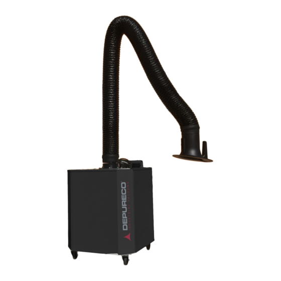
The purpose of the machine is to extract and filter welding fumes and metal smoothing dust produced by mechanical industry processing. The polluting elements are captured and carried towards the filter through rigid or flexible pipes connected to the hood. 4.3. OPERATING CYCLE DESCRIPTION AIRWELD AIRWELD WALL STAGE DESCRIPTION The air extracted through the pipe is conveyed by the fan in the body. -
Page 20: Technical Data
4.4. TECHNICAL DATA 4.4.1. PERFORMANCE 1,5/1,1 1,5/1,1 Power [HP/kW] Power supply voltage 3Ph [V] Power supply voltage 1Ph [V] 2,54 2,54 Consumption [A] 50/60 50/60 Frequency [Hz] Motor phase [Ph] 2846 2867 Type of fan PR-PRM 300 PR-PRM 300 Max flow rate [m3/h] 1400 1400 Nominal min flow rate [m3/h]... -
Page 21: Diagram And Electrical Values
4.4.2. DIAGRAM AND ELECTRICAL VALUES SIZE OF MOTOR CIRCUIT BREAKER SIZE AND TYPE OF MODELLO MACCHINA FUSE LINE (A) AIRWELD 1,8/2,5 AIRWELD WALL 1,8/2,5 AIRWELD USA - 220V - 1Ph 3,5/5 AIRWELD WALL USA - 220V - 1Ph 3,5/5... - Page 22 WIRING DIAGRAM 400V 50Hz 3Ph WIRING DIAGRAM 220V 60Hz 1Ph...
-
Page 23: Size Of Air Inlet
4.4.3. SIZE OF AIR INLET AIRWELD Input Ø [mm] 4.4.4. SIZE OF AIR OUTLET AIRWELD Output Ø [mm]... -
Page 24: Filter
4.4.5. FILTER AIRWELD Filter dimension [mm] Ø 325 x 400 Type of filter Cartridge Type of filtering fabric 100% Cellulose 7033 “L ” BIA rating Filtering surface [m Filtering rate [%] 4.5. SAFETY DEVICE DESCRIPTION The machine is equipped with a general ON-OFF switch with safety block. -
Page 25: Description Of Perimeter Areas
4.6. DESCRIPTION OF PERIMETER AREAS During installation, take into account the dimensions of any optional parts. AIRWELD... - Page 26 AIRWELD WALL...
-
Page 27: Information On Use
The machine is designed to operate with pressure filtering. Any other machine use must be authorised by DEPURECO S.r.l. in advance. In the absence of such written authorisation, the Manufacturer shall deny any liability for damage caused to people or property and the warranty on the line and the machines supplied shall cease. -
Page 28: Information On Adjustments
INFORMATION ON ADJUSTMENTS 6.1. RECOMMENDATIONS FOR ADJUSTMENTS The flow rate regulating gate is not an integral part of the machine. 6.2. FLOW RATE REGULATION To regulate the air flow rate, close the gate to decrease it. See paragraph “OPTIONAL FEATURES INSTALLATION METHODS”. -
Page 29: Maintenance Information
MAINTENANCE INFORMATION 7.1. RECOMMENDATIONS FOR MAINTENANCE INTERVENTIONS Carefully read the instructions in this manual before any maintenance intervention. Perform maintenance activities using the personal protective equipment described in the manual. 7.2. TABLE OF SCHEDULED MAINTENANCE INTERVALS Routine maintenance operations are to performed at the date shown in the table. OPERATION Check that the filtering efficiency is •... -
Page 30: Information On Troubleshooting
INFORMATION ON TROUBLESHOOTING The following information has the purpose of helping to identify the anomalies and restore the machine operation and efficiency. DEFECT CAUSE POSSIBLE SOLUTIONS The emitted air is not sufficiently Amount and kind of powder do not Redefine the project and replace match the ones in the project. - Page 31 Manufacturer or by the Authorised Assistance Centre. Change the filters using the protective equipment described in the manual. Prior to changing the filter, the motor or the fan, remove the optional part assembled on the extraction intake. 9.2. LIST OF REPLACEABLE COMPONENTS 9.2.1. STANDARD AIRWELD...
- Page 32 AIRWELD WALL POS. ELEMENT Cartridge filters code 7041061172 Rotary wheel Motor Circuit breaker switch Switch box Hour-meter Plug Electrical cable Instrument...
- Page 33 POS. ELEMENT Feed-through nut Feed-through TAKING DOWN AND PUTTING IN CARTRIDGE FILTERS STEP ACTION PICTURE Take the articulated arm or any other pipe down from the machine unit. Engage the brakes on the wheels.
- Page 34 Place the machine on its side, the one with the electric controls. Take out the screws that secure the cartridge to the surface.
- Page 35 STEP ACTION PICTURE Take the filter out and place it in sealed bags. 9.2.2. OPTIONAL POS. ELEMENTO Articulated extractor arm Polyester filtering cartridge Aluminium-coated filtering cartridge Teflon-coated filtering cartridge...
- Page 36 9.3. SCRAPPING DECOMMISSIONING The machine does not have any particular problems as regards to decommissioning. Proper care shall be taken to prevent unauthorised personnel from starting the machine. Comply with the laws in force in the country of use, for any legal and tax aspects (any reports, complaints, etc...).
Need help?
Do you have a question about the AIRWELD and is the answer not in the manual?
Questions and answers