
Related Manuals for Elvox Digibus Galileo Series


Summary of Contents for Elvox Digibus Galileo Series
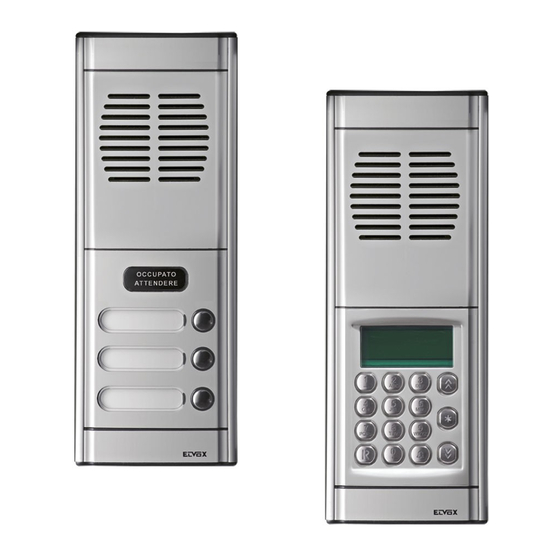
- Page 1 MODULES FOR ELECTRONIC VIDEO OR AUDIO ENTRANCE PANEL WITH KEYPAD AND NUMERICAL DISPLAY INSTALLATION AND CONNECTION MANUAL ART. 8942 ART. 8946 ART. 8946/C Product is according to EC Directive 89/336/EEC and following norms. Cod. S6I.894.20E Ed. 03 7/2006...
-
Page 2: Installation
DESCRIPTION FOREWORD The Galileo series of Digibus electronic entrance panels is designed to operate both on DigiBus systems with 4-digit codes (old type) and on DigiBus systems with 8-digit codes (new type). Operation with 4-digit codes is recommended only for existing installations which use this cod- ing system, otherwise use the 8-digit codes for new installations, regardless of the number of internal units. - Page 3 COMPONENTS MODULES Art. 8942 Art. 8942 is a pack containing 3 basic electronic modules for executing an audio entrance panel with keypad and numerical display with 8 dig- its. The three modules are: one audio module, one module with display and numerical keypad and one name-tag module for 13 names, with terminal blocks for connecting the panel.
- Page 4 COMPONENTS SUPPLEMENTARY MODULE Art. 8A1N Supplementary module with LED back-lit name-tag holder (for 13 names), to be added to the basic electronic modules for expansion of the entrance panel. Made in ITALY The back of the panel accommodates the two terminals LA (negative) and LB (positive) for pow- ering the LEDs, to be connected as shown in the wiring diagrams.
- Page 5 COMPONENTS ACCESSORIES: MODULE HOLDER FRAMES ACCESSORIES: FLUSH-MOUNTED BACK BOXES Thickness 1 horizontal mod- No. vertical 1 horizontal module No. vertical Thickness 50 mm ule (width 88 mm) m o d u l e s (width 101 mm) modules (height) 21 mm (height) 1 module 1 module...
- Page 6 COMPONENTS ACCESSORI: BEZELS No. horizontal modules (width) No. Vertical modules (height) No. Vertical Thickness m o d u l e s 2 mm 1 module 2 modules 3 modules 4 modules (height) (108 mm) (208 mm) (308 mm) (408 mm) 1 module (169 mm) Art.
- Page 7 COMPONENTS ACCESSORIES: FRAMES WITH RAINPROOF COVER No. horizontal modules (width) No. Vertical Thickness m o d u l e s 4 modules 38 mm 1 module 2 modules 3 modules (height) (418 mm) (118 mm) (218 mm) (318 mm) 1 module (178 mm) Art.
- Page 8 COMPONENTS ACCESSORIES: SURFACE-MOUNTED WALL BOXES No. horizontal modules (width) Thickness No. Vertical 50 mm m o d u l e s 3 modules 4 modules 1 module 2 modules (height) (318 mm) (418 mm) (118 mm) (218 mm) 1 module (178 mm) Art.
- Page 9 ASSEMBLY FITTING THE MODULES IN THE MODULE HOLDER FRAMES Open the module holder frame by inserting a screwdriver in the two slits in the back of the bottom end fixing element (fig. 1A and 1B). Remove the bottom end fixing element (fig. 2). - Fit the modules in the module holder frame and the plate of the module with the name-tag holder.
- Page 10 - If using the bezels, tighten the screws joining the end fixing ele- ments to the bezel and the boxes. - Fasten the plates to the end fixing elements and fix them using the special ELVOX wrenches (fig. 10A - 10B - 10C). Fig 9A Fig 9D...
- Page 11 ASSEMBLY Fig 7B Fig 7C Fig 8B Fig 8C Fig 9B Fig 9C Fig 10B Fig 10C...
- Page 12 - Route the flat cables joining the modules between the boxes and the bezels. Fasten the plates to the end fixing elements and fix them using the special ELVOX wrenches (fig. 15). Fig 11 Fig 15...
-
Page 13: Wiring The Modules
ASSEMBLY WIRING THE MODULES Connect module art. 8A09 or 8A19 or 8A19/C to module 8A15, by means of the flat cable and connector CN1 (Fig. 17-18). Connect module art. 8A0N to module 8A09 or 8A19 or 8A19/C, by means of the flat cable and connector CN2 (Fig. 17-18). The supplementary modules art. - Page 14 PROGRAMMING PRELIMINARY OPERATIONS Having installed and connected all the devices, power up the system and check the LEDs on the power supply units to make sure that they all supply power. Before carrying out any programming operations on the devices, wait for at least ten seconds from the moment at which the sys- tem is powered up.
- Page 15 PROGRAMMING ENTRANCE PANEL TECHNICAL PARAMETERS TABLE No. Parameter Abbreviation on Abbreviation on Minimum Maximum Default Description When to change the value entrance panel display programmer display value value English English Initial User INITI_US Initial User 99999999 1 Lowest call number (filter on the codes Required in building complexes.
- Page 16 PROGRAMMING Description of functions: - Initial User "INITI_US" (1) and Final User "FINA_US" (2). To be programmed in the case of a system for a building complex. The two val- ues must be set only on the secondary entrance panels. These two parameters serve to switch the secondary entrance panel to the engaged state when a call is being made from another entrance panel or from a switchboard with a number between the lowest and the highest num- ber.
- Page 17 PROGRAMMING - Enable camera "CAMER_E" (13). To be programmed with type 8946 entrance panels. Indicates that the entrance panel is of video type equipped with a camera. This makes it possible to manage switch-on and switch-off of the monitors in the system in the correct way. - Enable sound in entrance panel "P_SOU_E"...
- Page 18 PROGRAMMING - Enables the window above "A_FINUP" (27). If the parameter is enabled, the parameters "initial user" (1) and "final user" (2) are used for filtering the codes descending from terminal 1 to terminal 6 of the secondary entrance panels. This function is for use in systems for build- ing complexes in which there are several secondary entrance panels connected in double parallel (as well as the connection of terminals 1, terminals 6 are also connected).
- Page 19 OPERATION ENTRANCE PANEL OPERATION Call from entrance panel to user; on the keypad, dial the number of the user in question and press "C". When you press "C" the entrance panel will send the call to the interphone. If parameter "14" is enabled, the call signal sent to the interphone will be repeated by the entrance panel receiver.
- Page 20 WIRING DIAGRAM MINIMAL CONDUCTOR SECTION (mm Conductors Ø up to 50 m. Ø up to 100 m. Ø up to 200 m. 4-5-9 0,75 mm 1 mm 1,5 mm + - and lock 1 mm 1,5 mm 2,5 mm Others 0,5 mm 0,75 mm 1 mm...
- Page 21 B- Additional push-button for lock C- Electric lock 12V A.C. D- Additional modules range 8A..Phone Phone Art. 887B Art. 887B Art. 887B/1 Art. 887B/1 Phone Phone Art. 6204 Art. 6204 Mains Power supply Art. 6941 CH S F2 3 S1 15 ELVOX...
- Page 22 C- Electric lock 12V A.C. Art. 8877 Art. 8877 D- Additional modules range 8A. E- Floor distributor Art. 949B... Phone Phone Art. 6201 Art. 6201 Mains Power supply Art. 6941 CH S F1 F2 3 4 5 S1 15 O ELVOX...
- Page 23 WIRING DIAGRAM SIMPLE RESIDENTIAL INSTALLATION WITH TWO OR MORE PANELS IN PARALLEL. Ref. diagram p2709...
- Page 24 WIRING DIAGRAM RESIDENTIAL INSTALLATION WITH ONE MAIN PANEL AND TWO OR MORE SECONDARY PANELS. Ref. diagram pe2765 Mains Mains INTERPHONE INTERPHONE CABLE RISER CABLE RISER Power supply Power supply 1 3 4 5 1 3 4 5 Art. 6942 Art. 6942 CH S F1 F2 3 4 5 S1 15 O CH S F1 F2 3 4 5...
- Page 25 WIRING DIAGRAM RESIDENTIAL INSTALLATION WITH TWO OR MORE MAIN PANELS AND TWO OR MORE SECON- DARY PANELS. Ref. diagram pe2766 A- Entrance panel Art. 8942/... - 8943/.. E- Transformer Art. M832 B- Aditional push-button for lock F- Power supply Art. 6942 C- Electric lock 12V A.C.
- Page 26 WIRING DIAGRAM MONITOR CABLE RISER WITH UNITS EQUIPPED WITH INTERNAL DIGITAL SIGNAL DECODING. Ref. diagram pv4407 The riser shown must be included in all the video interphone diagrams in this collection (this diagram is an alternati- ve to diagram pv4440) MONITOR CABLE RISER 1 3 4 5 - +...
- Page 27 WIRING DIAGRAM MONITOR RISER WITH FLOOR DISTRIBUTOR ART. 949B Ref. diagram pv4440 The riser shown must be included in all the video interphone diagrams in this collection (this diagram is an alternati- ve to diagram pv4407) MONITOR CABLE RISER 1 3 4 5 - + Monitor Monitor 75ohm...
- Page 28 Art. 6948 CH S F1 F2 3 4 5 + 15 O VIDEO DISTRIBUTOR Art. 5556/004 Art. 6554 A- Video entrance panel Art. 8945/... - 8946 B- Additional push-button for lock C- 12V~ electric lock D- Additional modules range 8A. ELVOX...
- Page 29 CH S F1 F2 3 4 5 + 15 0 A- Video entrance panel Art. 8945/... - 8946- 8946/C... B- Additional push-button for lock C- 12V~ electric lock D- Additional modules range 8A. E- Digital distributor Art. 949B 88888888 ELVOX...
- Page 30 WIRING DIAGRAM 18- SIMPLE RESIDENTIAL INSTALLATION WITH TWO OR MORE PANELS IN PARALLEL Ref. diagram pv2712R5...
- Page 31 MONITOR CABLE RISER Power supply Power supply Art. 6948 Art. 6948 M2 V2 F1 F2 M2 V2 V1 M1 88888888 88888888 ELVOX ELVOX Cable riser Cable riser 1 3 4 V V V V Distributor Art. 5556/004 - 6554 Mains Mains...
- Page 32 M2 V2 F1 F2 M2 V2 F1 F2 5 + - S1 15 88888888 88888888 75 Ohm 75 Ohm ELVOX ELVOX ELVOX ELVOX Cable riser Cable riser 1 3 4 V V V V Distributor Art. 5556/004 - 6554 Mains...
- Page 33 CH S F1 F2 3 4 5 + 15 0 M2 V2 V1 M1 88888888 88888888 75ohm ELVOX A- Main entrance video panel Art. 8945/... - 8946 Cable riser Cable riser A1- Secondary external video panel 1 3 4 V V V V Distributor Art.
- Page 34 Art. 6948 tional functions M2 M2 V2 V2 V1 V1 M1 M1 +I +I CH CH F1 F1 F2 F2 3 3 4 4 + + - - 15 15 O O 3 4 5 Additional function Additional function ELVOX...
- Page 35 APPENDIX A DESCRIPTION OF TERMINALS Art. 8A0N Terminals Description Comment Control terminal for monitor switch-off. The terminal is activated to switch off the monitors connected to the cable riser, at the beginning of a call and at the end of the conversation. The terminal must be connected to the power supply unit 6948 if required by the diagram.
- Page 36 Tel. 049/9202511 r.a. - E-mail: filialemilano@elvoxonline.it Phone international... 39/49/9202511 Fax Italia 049/9202603 FILIALE TOSCANA: Telefax Export Dept... 39/49/9202601 Via Lunga 4/R 50142 FIRENZE ELVOX INTERNET SERVICE Tel. 055/7322870 - Telefax. 055/7322670 E-mail: info@elvoxonline.it E-mail: filialetoscana@elvoxonline.it http://www.elvox.com E-mail export dept: elvoxexp@elvoxonline.it...
Need help?
Do you have a question about the Digibus Galileo Series and is the answer not in the manual?
Questions and answers