Table of Contents
Advertisement
Available languages
Available languages
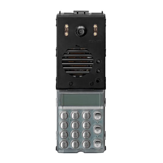
Unità Due Fili audio tastiera acciaio / Unità Due Fili colori tastiera acciaio
Due Fili audio keyboard unit in stainless steel / Due Fili colors keyboard unit in stainless steel
1
2
3
1
2
3
ABC
DEF
4
6
5
GHI
MNO
JKL
7
8
9
PQRS
TUV
WXYZ
0
R
+
Manuale installatore
Installer guide
1
2
3
1
2
3
ABC
DEF
4
6
5
GHI
MNO
JKL
7
8
9
PQRS
TUV
WXYZ
0
R
+
Advertisement
Table of Contents

Related Manuals for Elvox Due Fili Plus


Summary of Contents for Elvox Due Fili Plus
- Page 1 Manuale installatore Installer guide PQRS WXYZ PQRS WXYZ Unità Due Fili audio tastiera acciaio / Unità Due Fili colori tastiera acciaio Due Fili audio keyboard unit in stainless steel / Due Fili colors keyboard unit in stainless steel...
-
Page 2: Table Of Contents
O manual de instalador pode ser baixado a partir de www.vimar.com Descrizione Le unità elettroniche 13F4 (audio) e 13F7 (video) sono impiegabili esclusivamente su impianti con tecnologia Due Fili Plus. Sono dotate di tastiera alfanumerica e nella versione video, di TLC con gruppo illuminatore a LED. -
Page 3: Operazioni Preliminari
Figura2 Unità elettronica con telecamera Figura1 Regolazione manuale orizzontale e verticale Cablaggio per collegamento morsettiera Reset Tasto programmazione Cablaggio per collegamento moduli supplementari PQRS WXYZ Morsettiera Operazioni preliminari CN1) Connettore per unità elettronica. Negli impianti con una sola unità elettronica l’identificativo ID deve essere CN2) Connettore per programmatore art. -
Page 4: Valore Di Default Dei Parametri
Collegamento di una TLC esterna tipo TVCC su unità elettronica audio Per collegare una TLC esterna tipo TVCC su un’unità elettronica audio (13F4), è necessario configurare l’unità elettronica come fosse videocitofo- nica. Questo tipo di configurazione avviene rimuovendo il ponticello SA. Per rimuovere il ponticello deve essere sollevata la tastiera alfanumerica Posizione ponticello inserito configurazione come unità... - Page 5 NOTA: le informazioni che compaiono tra parentesi quadra, si riferiscono distinguere una unità elettronica MASTER e le altre come targhe SLAVE, a dati del “Due Fili Plus” . indipendentemente dal modello di unità elettronica (alfanumerica, pulsanti, fuoriporta). Tutte le targhe vengono fornite con l’impostazione unità elettro- NOTA: in figura 7 la lettera V dopo 13F4 o 13F7 corrisponde alla configura- nica MASTER (ID = 1).
- Page 6 Procedura di configurazione: TASTO SIMBOLO - Eseguire la sequenza di attribuzione del codice di identificazione ID, come ripor- tato nelle istruzioni del posto interno da codificare. <spazio>1@.,:;?!()<> - Nel momento in cui il posto interno entra in programmazione, sul display della unità elettronica MASTER appare il messaggio: ABC2abcÁÀÃÅÄÆÇÈáàãåäæçè...
- Page 7 SEGNALAZIONE OCCUPATO-ATTENDERE REGOLAZIONE VOLUMI IN CONVERSAZIONE È possibile eseguire le regolazioni del volume esterno ed interno durante Quando sul display compare l’indicazione OCCUPATO, l’unità elettronica una conversazione. Le regolazioni sono possibili solamente dopo aver atti- è disabilita per l’esecuzione di chiamate, perchè è in atto un’altra chiamata vato la funzione come descritto di seguito.
- Page 8 1.0 - LINGUA MESSAGGI Indica la modalità di visualizzazione dei messaggi in lingua italiana. Per modificare la lingua Lingua Messaggi impostata premere sulla tastiera il numero corrispondente alla lingua come indicato in tabella 1. TASTO LINGUA italiano inglese greco francese tedesco spagnolo portoghese...
- Page 9 1.8 - NUMERO CIFRE CODIFICA Imposta il tipo di codifica per le chiamate verso i posti interni nella configurazione BUS verticale/orizzontale: - Codifica sequenziale (3 cifre) è irrilevante). - Codifica a 4 cifre, in questa configurazione i codici possono essere da 1 a 4 cifre. - Codifica a 8 cifre, in questa configurazione i codici possono essere da 1 a 8 cifre.
- Page 10 2.3 CHIAVI F1 Chiavi F1 È possibile registrare fino a 1000 codici diversi, composti da massimo 8 cifre, per comandare F1 direttamente dalla tastiera dell’ unità elettronica stessa. Utilizzare i pulsanti per selezionare una delle 1000 chiavi. In corrispondenza della chiave interessata, premere il tasto per entrare in modifica.
- Page 11 TASTO SIMBOLO Premere il tasto per confermare la modifica. Dopo la conferma la unità elettronica verificherà se il nome inserito sia usato da un altro <spazio>1@.,:;?!()<> utente. Se è già usato visualizzerà “..usato da ...” e sarà necessario introdurre un altro nome, altrimenti visualizza il messaggio “Fatto!”. Se ABC2abcÁÀÃÅÄÆÇÈáàãåäæçè...
- Page 12 3.6 VOLUME INTERNO È Volume interno Premere il tasto per entrare in modifica volume. Premere i pulsanti per aumentare o diminuire il volume. Premere il tasto per confermare la modifica. Alla conferma della modifica viene visualizzato il messaggio “Fatto!”. Default = 6 3.7 BILANCIAMENTO Bilanciamento È...
- Page 13 4.4 SERRATURE COMUNI Questo parametro permette l’apertura indiretta della serratura, in coincidenza con l’apertura della serratura di Seq. Autoac. 1 un’altra unità elettronica, comandata da un posto interno. Si può associare l’apertura indiretta a 4 differenti unità elettroniche. una unità elettronica (in questo caso la prima su quattro possibili scelte) per il comando della cui serratura anche il posto esterno corrente deve attivare la propria: Orologio Per confermare premere il tasto...
- Page 14 Utilizzare il tasto per cancellare l’ultimo carattere inserito. Premere il 5.3 - ULTIMA CHIAVE A TEMPO E’ simile alla precedente, solo che si riferisce all’ultima chiave valida. tasto per confermare la modifica. Alla conferma della modifica viene visualizzato il messaggio “Fatto!”. Durante questa fase, è...
- Page 15 5.6 - PULSANTE 6120 DESCRIZIONE DEI CODICI A TEMPO Questa sezione permette di attribuire la configurazione del modulo pulsanti Le unità elettroniche 13F7 sono equipaggiate con il modulo orologio, che permette di realizzare la funzione di abilitare un certo numero di Chiavi zioni di prodotto del modulo pulsante.
-
Page 16: Safety Instructions For The Installer
Contents Safety instructions for the installer ............Directives ....................Description ..................................Preliminary procedures .......................................... 17 Default value of parameters ......................................... 18 ........................................19 Wiring diagrams ............................................ 30 Wiring versions ............................................32 Description Electronic units 13F3 (audio) and 13F5 (video) can be used only in Plus 2-wire systems. Units are equipped with an alphanumeric keypad, and in the video version, with a LED lighting unit. -
Page 17: Preliminary Procedures
Figure2 Electronic unit with camera Figure1 Manual horizontal and vertical adjustment Wiring for terminal block connection Reset Programming button Wiring for connection of ad- ditional modules PQRS WXYZ Terminal block Preliminary procedures CN1) Connector for electronic unit. In systems with just one electronic unit, the ID must be MASTER. CN2) Connector for programmer art. -
Page 18: Default Value Of Parameters
Connection of a CCTV type external camera to an audio electronic unit To connect an external CCTV camera to an audio electronic unit (13F4), the electronic unit must be configured as if it were intended for video entryphone use. This type of configuration is accomplished by removing the SA jumper. To perform the operation, raise the alphanumeric keypad Jumper position connected configuration as audio electronic unit (13F4) - Page 19 NOTE: if the password is wrong, the electronic unit exits the procedure and PARAMETER CONFIGURATION reverts to at-rest status. The operation must be repeated. Having accessed the configuration procedure, the first message to appear is Parameters can be reconfigured, and the procedure can be performed after a prompt to select the language the “entrance panel”...
- Page 20 Configuration procedure: BUTTON SYMBOL - Run the ID code number allocation sequence, as indicated in the instructions for the indoor unit to be coded. <space>1@.,:;?!()<> - When the indoor unit goes into programming mode, the display of the MA- ABC2abcÁÀÃÅÄÆÇÈáàãåäæçè STER electronic unit shows this message: DEF3defïÉÈÊÌéèêì...
- Page 21 ENGAGED - PLEASE WAIT MESSAGE ADJUSTING VOLUME DURING CONVERSATION When the message ENGAGED appears in the display, the electronic unit BOTH the internal and the external volume can be adjusted during a con- is disabled from making calls, as another call from another electronic unit versation.
- Page 22 1.0 - MESSAGE LANGUAGE Indicates the language selected for messages displayed by the system. To change the language, Message language press the number on the keypad corresponding to the required language, as indicated in table 1. BUTTON LANGUAGE italiano inglese greco francese tedesco...
- Page 23 1.8 - NUMBER OF CODING DIGITS Set the type of coding for calls to indoor units in Vertical/Horizontal Bus configuration: - Sequential coding (3 digits), digits is irrelevant). - 4 digit coding, in this configuration, codes can be from 1 to 4 digits. - 8 digit coding, in this configuration, codes can be from 1 to 8 digits.
- Page 24 2.3 F1 CODES F1 codes UP to 1000 different codes can be recorded, comprising 8 digits maximum, to control F1 directly from the keypad of the electronic unit. Use the buttons to select one of the 1000 passwords. Having located the re- quired password, press the button to change the value.
- Page 25 BUTTON SYMBOL Press the button to confirm the change. After confirmation, the electronic unit will check whether or not the name entered is already <spazio>1@.,:;?!()<> taken by another user. If already taken, the message “..used by ...” will appear, and another name must be entered, otherwise the message ABC2abcÁÀÃÅÄÆÇÈáàãåäæçè...
- Page 26 3.6 INTERNAL VOLUME Internal volume Press to enable changes to the volume setting. Press the buttons to increase or reduce the volume. Press to confirm the change. When the change is confirmed, the message “Done!” will appear. Default = 6 3.7 BALANCING Balancing This adjusts the audio compensation between input channel and output channel (in order to eliminate any...
- Page 27 4.4 COMMON LOCKS This parameter allows the release of the lock indirectly, and at the same moment as the lock of another electronic Self-start sequence. 1 unit is released, from an indoor unit. Indirect release can be associated with 4 different electronic units Type the the first of four possible options) for which the lock release is dependent on the lock of the current entrance panel being activated.
- Page 28 5.3 - LAST TIMED CODE Use the button to cancel the last character entered. Press Similar to the code described above, but referring to the last valid code. confirm the change. When the change is confirmed, the message “Done!” will appear. During this procedure, a “notes” function can be used to help with duplication of the codes.
- Page 29 5.6 - BUTTON 6120 DESCRIPTION OF TIMED CODES 13F7 electronic units are equipped with the clock module, which provides module. An ID code must be attributed to the button module (see product the function of enabling a certain number of Lock Codes, F1 Codes and F2 instructions for the button module).
-
Page 30: Schemi Di Collegamento
Schema di collegamento unità elettronica singola audio o video (SI435) Wiring diagram for single audio or video electronic unit (SI435) C - Unità elettronica audio o video / Audio or video electronic unit F - Alimentatore di sistema / System power supply unit Montante L - Serratura elettrica 12 Vdc / Electric lock 12 Vdc Cable riser... - Page 31 Schema di collegamento di più targhe video o più targhe video e targhe audio (SI685) Wiring diagram for multiple video entrance panels or multiple video and audio entrance panels (SI685) D - Unità elettroniche video / Video electronic units F - Alimentatore di sistema / System power supply unit L - Serratura elettrica 12 Vdc / Electric lock 12 Vdc P - Comando apriporta / Door release control X - Cavo twistato / Twisted cable...
-
Page 32: Varianti Di Collegamento
Variante/Version Unità elettronica con cartello numero civico retroilluminato Electronic unit with backlit house number plate. Montante Cable riser EXT+ EXT- VLED +12V Circuito di illuminazione numero civico. Uti- lizzare solo circuito fornita nella confezione. Backlit house number plate lighting circuit Only use the lighting supplied Fare collegamenti Perform wiring... - Page 33 Serratura elettrica 12 Vdc / Electric lock 12 Vdc Comando apriporta / Door release control P2 - Sensore porta aperta (N.O. a porta chiusa) / Door open sensor (N.O. with door closed) Cavo twistato Due Fili Elvox / Elvox Twisted Pair Cable EXT+ EXT-...
- Page 34 Variante/Version Collegamento funzioni ausiliarie F1 e F2 / Connection of auxiliary functions F1 and F2. 1 2 3 4 5 (MAX 3A 230V) (MAX 3A 230V) EXT+ EXT- FUNZIONE FUNZIONE VLED AUSILIARIA AUSILIARIA +12V D - Unità elettronica / electronic units L - Serratura elettrica 12 Vdc / Electric lock 12 Vdc Q - Relè...
- Page 35 REGOLE D’INSTALLAZIONE INSTALLATION RULES L’installazione deve essere effettuata con l’osservanza delle disposizioni Installation should be carried out observing current installation regulations regolanti l’installazione del materiale elettrico in vigore nel paese dove i for electrical systems in the country where the products are installed. prodotti sono installati.
- Page 36 Fax (Export) +39 0424 488 709 www.vimar.com ELVOX - Marostica - Italy...
Need help?
Do you have a question about the Due Fili Plus and is the answer not in the manual?
Questions and answers