
Related Manuals for Extron electronics MLS 608 D Series


Summary of Contents for Extron electronics MLS 608 D Series
- Page 1 User Guide AV SWITCHERS MLS 608 D SERIES AV Switchers with ProDSP ™ (with the MTP/HDMI U R receiver) MLS 608 D SA MTP/HDMI U R 68-1893-01 Rev. A 12 11...
- Page 2 Precautions Safety Instructions • English Warning Power sources • This equipment should be operated only from the power source indicated on the product. This This symbol is intended to alert the user of important operating and maintenance equipment is intended to be used with a main power system with a grounded (neutral) conductor. The third (servicing) instructions in the literature provided with the equipment.
- Page 3 FCC Class A Notice This equipment has been tested and found to comply with the limits for a Class A digital device, pursuant to part 15 of the FCC Rules. Operation is subject to the following two conditions: This device may not cause harmful interference. This device must accept any interference received, including interference that may cause undesired operation.
- Page 4 Selectable items, such as menu names, menu options, buttons, tabs, and field names are written in the font shown here: From the File menu, select Click the button. Copyright © 2011 Extron Electronics. All rights reserved. Trademarks All trademarks mentioned in this guide are the properties of their respective owners.
-
Page 5: Table Of Contents
Installation From the DVD ......44 Features .............. 1 Installation from the Website ......45 Controlling the MLS 608 D Series Switcher ..3 Starting the DSP Configurator ......45 MLS 608 D SA Application Diagram Using the DSP Configurator Software ....47 ................. - Page 6 MLS 608 D Series • Contents...
-
Page 7: Introduction
Introduction This manual contains information about the Extron MLS 608 D Series of AV switchers with instructions for experienced installers on how to install, configure, and operate it. In this manual the terms “MLS 608 D Series switcher,” “AV switcher,” and “switcher” are used interchangeably and refer to any of the MLS 608 D Series models. - Page 8 Because the buttons illuminate, they are helpful for presenters in low-light environments. Audio switching and output volume control — The MLS 608 D Series features audio switching for eight input sources, and provides master volume control and muting. Three balanced or unbalanced outputs are available, two on the MLS 608 D switchers, the third on the MTP/HDMI U R.
-
Page 9: Controlling The Mls 608 D Series Switcher
Internal universal power supply — The 100-240 VAC, 50-60 Hz, international power supply provides worldwide power compatibility. Controlling the MLS 608 D Series Switcher All MLS 608 D series switchers can be controlled using one or more of the following methods: The front panel controls. -
Page 10: Mls 608 D Sa Application Diagram
W ER M AX 0. 8A HDMI + Audio Projector HDMI + Audio Document Camera Laptop Blu-ray Player Figure 1. MLS 608 D SA and MTP/HDMI U R, with an Optional MLC 226 IP DV+ MLS 608 D Series • Introduction... -
Page 11: Installation
Installation This section contains installation information for an MLS 608 D Series device and covers the following subjects: UL/Safety Requirements Mounting the MLS 608 D Series Switcher UL/Safety Requirements The Underwriters Laboratories (UL) requirements listed below pertain to the safe installation and operation of this AV Switcher. -
Page 12: Mounting The Mls 608 D Series Switchers
UL Guidelines for Rack Mounted Devices The following Underwriters Laboratories (UL) guidelines pertain to the safe installation of the MLS 608 D Series switcher in a rack. Elevated operating ambient temperature — If installed in a closed or multi-unit rack assembly, the operating ambient temperature of the rack environment may be greater than room ambient temperature. -
Page 13: Rear Panel Connections
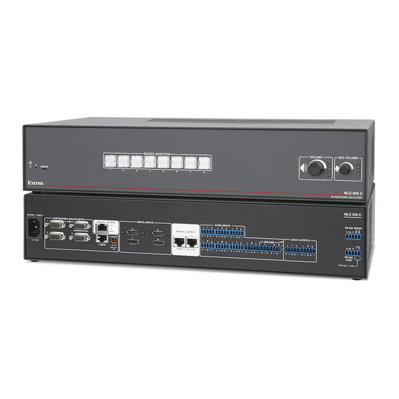
This section describes the rear panel features and how to connect the cables to the MLS 608 D and to the MTP/HDMI U R as applicable. MLS 608 D Series Rear Panel Features This illustration shows all possible features of the MLS 608 D Series. MLS 608 D SA MLS 608 D SA... -
Page 14: Power, Analog, And Digital Connections
The EDID can be manually assigned using SIS commands or via DSP Configurator. The default settings are 720p at 60 Hz for digital inputs, and 1024x768 at 60 Hz for analog inputs. MLS 608 D Series • Rear Panel Connections... - Page 15 The MLS-to-MTP input and output transmission distances for CAT 5, 5e, CAT 6, and CAT 7 cable vary depending on the signal type, resolution and the quality of cable used. See the table on page 10 for distances. MLS 608 D Series • Rear Panel Connections...
- Page 16 This supplies sufficient power via the MLS device to fully power the MTP unit. NOTE: When the power save mode is set to on, this port also turns off. Tie Wrap Captive Screw Connector Figure 5. Wiring the MLS 608 D Power Output Connector MLS 608 D Series • Rear Panel Connections...
- Page 17 LockIt lacing bracket to be placed over it. Place the LockIt lacing bracket on the screw and against the HDMI connector, then tighten the screw to secure the bracket. MLS 608 D Series • Rear Panel Connections...
- Page 18 1080p @ 60 Hz MLS 608 D MTP/HDMI U R SOURCE SELECTION VOLUME MIC VOLUME LAPTOP Blu-ray ANALOG CONFIG SIGNAL LEVEL PEAKING DIGITAL SIGNAL AUDIO RS-232 MLS 608 D AV Switcher MTP/HDMI U R MLS 608 D Series • Rear Panel Connections...
- Page 19 Feed each individual wire into the appropriate slot of the RJ-45 connector and crimp the cable in the normal manner, folding the tangs at the end of the connector over the shielded tape. Crimped Connector Figure 8. Crimped RJ-45 Connector MLS 608 D Series • Rear Panel Connections...
-
Page 20: Audio And Rs-232 Connections
For unbalanced audio, connect the sleeve(s) to the ground contact. DO NOT connect the sleeve(s) to the negative (-) contacts NO Ground Here Ring Sleeve(s) Sleeve(s) NO Ground Here Ring Unbalanced Output Balanced Output MLS 608 D Series • Rear Panel Connections... - Page 21 MLS and to ground at both ends. Power ports MLS PWR RS-232 12V Figure 9. Wiring the MLS 608 D RS-232 Host Port to an MLC 226 IP MLS 608 D Series • Rear Panel Connections...
- Page 22 MTP/HDMI U R RS-232 Input port Display device RS-232 port Rx Tx Ground RS-232 Device pins Figure 10. Wiring the MLS 608 D RS-232 Insert Port (showing RS-232 Flow Path to the Display Device) MLS 608 D Series • Rear Panel Connections...
-
Page 23: Mtp/Hdmi U R Connections
signal. Wire connector as shown above. NOTE: The audio signal is detected on the MTP input and then is distributed to the audio connector for output. MLS 608 D Series • Rear Panel Connections... - Page 24 Do not tin the power supply leads before installing them in the direct insertion connector. Tinned wires are not as secure in the connectors and could be pulled out. When power is applied the front panel power LED lights. MLS 608 D Series • Rear Panel Connections...
-
Page 25: Power Save Mode
NOTES: • If the switcher is in the standby state, and power is re-cycled on the unit, it powers back up into the normal state, and not into the standby state. • The switcher is not ENERGY STAR ® qualified. MLS 608 D Series • Rear Panel Connections... -
Page 26: Operation
Factory firmware must be re-uploaded if that is the version to be used. • If you do not want to update the firmware, recycling the power reinstates the firmware version used before the Mode 1 reset. MLS 608 D Series • Operation... - Page 27 By default it controls the volume of the three program outputs together. NOTE: y default, program output 2 has a fixed output level. Group Master 1 Group Master 2 Figure 12. Group Masters 1 and 2 Assigned to Front Panel Adjustment Knobs MLS 608 D Series • Operation...
-
Page 28: Using Edids
720p at 60 Hz, 2-channel PCM audio for digital inputs. NOTES: To work with the EDID Minder, update the EDID table, and import or export • EDID data, the MLS 608 D must be connected in Live mode. MLS 608 D Series • Operation... - Page 29 1360x768, 2-ch PCM Audio 1366x768, 2-ch PCM Audio 1440x900, 2-ch PCM Audio 1400x1050, 2-ch PCM Audio 1600x1200, 2-ch PCM Audio 1680x1050, 2-ch PCM Audio 1920x1200, 2-ch PCM Audio Figure 13. EDID Table with SIS Commands MLS 608 D Series • Operation...
-
Page 30: Automatic Edid Mode (Digital Output Only)
To save the analog output EDID information to the User 1 or User 2 location in the EDID table: Connect the display to the local analog output on the MLS 608 D Series switcher. Start DSP Configurator, if it is not running already, and connect to the device in the Live mode. -
Page 31: Importing Edid Data
To export EDID data: From the Tools menu, select Configure EDID. The EDID Configuration dialog box opens. Click Export EDID. The Export EDID dialog box opens (see figure below). Figure 15. Export EDID Dialog Box MLS 608 D Series • Operation... -
Page 32: Updating The Edid Table
Once the table is updated, the new EDIDs can be assigned to the relevant inputs as desired. MLS 608 D Series • Operation... -
Page 33: Optimizing Audio - An Overview
NOTE: See the "Workspaces Overview" section in the MLS 608 D Series book in the DSP Configurator Help File, for more information about these workspaces. MLS 608 D Series • Operation... -
Page 34: Dsp Signal Chain
• Inputs 1 through 4 are analog (ANG GAIN block). • Inputs 5 through 8 are digital (DIG GAIN block) but can be configured to accept either a digital (default) or an analog 2-channel input stream. • Input 4 is a mono input MLS 608 D Series • Operation... - Page 35 (0.0 dB). Delay (DLY) — Channel delay can be set by feet or meters modified by an air temperature parameter, or by direct time insertion from 0 - 200 ms. MLS 608 D Series • Operation...
- Page 36 This lowers the level of microphones and program material (based on a source signal from another microphone) for the duration of the signal that is present at the source microphone. Pre-Mixer Gain (GAIN) — Pre-mixer matrix gain control with a range of -100 to +0 dB. MLS 608 D Series • Operation...
-
Page 37: Building Blocks - An Overview
-17 dBFS (+4 dBu) Table Mics - Goosenecks 74 dBSPL 2 feet -17 dBFS (+4 dBu) Ceiling Mics 74 dBSPL 5 feet -17 dBFS (+4 dBu) Handheld Mics 74 dBSPL 0.5 feet -17 dBFS (+4 dBu) MLS 608 D Series • Operation... - Page 38 RTA was an electrical facsimile of the average acoustic response of the speakers. Parametric filters were then employed on the DSP to flatten the response curve on the RTA. Those filters were then saved into the building block for that speaker type. MLS 608 D Series • Operation...
- Page 39 Click the desired output channel building block in the list. The Building Blocks dialog box closes and the output channel building block loads all pre-configured processor blocks and gives a name to the channel. After inserting a building block, you can modify the processor blocks if desired. MLS 608 D Series • Operation...
- Page 40 To delete a folder and the associated building blocks, select the folder from the list and click the icon. - or - To delete an individual building block, right-click the listed building block and select Delete from the drop-down menu. MLS 608 D Series • Operation...
-
Page 41: Group Masters - An Overview
Output Volume — A mute control that globally mutes all output volume gain points. The default mute status is unmuted. The MLS 608 D Series front panel Program Volume knob controls the Program Volume group, and the front panel Mic Volume knob controls the Mic Volume group. While these groups cannot be deleted, group membership can be modified (see the Configuring Groups subsection below). - Page 42 Configuring Groups For an MLS 608 D Series device, five group masters are pre-configured and relate to program volume, mic volume, output bass, output treble, and volume mute. These groups cannot be deleted; however, group membership can be modified. To modify a pre-configured group: From the Tools menu, select Configure Groups.
- Page 43 After you add a new group and click Apply in the Configure Groups dialog box, the Group Controls window refreshes to display the added control. See the "Configuring Groups" section above for the procedure to add and configure groups. MLS 608 D Series • Operation...
- Page 44 The soft limit resolution is 0.1 dB. Click within the relevant Group Master fader areas (program volume, mic volume, output bass, output treble) to bring focus to the fader, then use the following key combinations. MLS 608 D Series • Operation...
- Page 45 Available Group Members section of the Configure Groups dialog box. After creating the group, the control dialog boxes for each group member change from displaying membership in a single group to displaying membership in multiple groups. MLS 608 D Series • Operation...
-
Page 46: Optimizing Video - An Overview
Settings dialog box appears (see image at right). Observe the oscilloscope (or monitor) with a critical eye and adjust the level using the slider. Adjust the peaking by using the up and down arrows. Disconnect test equipment when finished. MLS 608 D Series • Operation... -
Page 47: Setting The Skew On The Mls 608 D
The Output MTP Settings dialog box appears. Toggle the Pre-peak box on or off as desired. NOTE: For other video configurations, such as RGB delay, or input video format swapping, see the DSP Configurator Help file. MLS 608 D Series • Operation... -
Page 48: Firmware Upgrades
Firmware File field associated with the selected device. The Choose Firmware File dialog box opens. Browse to and select the device-specific firmware file that has been downloaded on your PC. Valid firmware files have an S19 file extension. MLS 608 D Series • Operation... - Page 49 Exit Firmware Loader. The DSP Configurator workspace restores itself and returns you to Emulate mode because connection is lost after a firmware upload. To reconnect to the device click the Live button in the application window or from the Tools menu, select Connect to Device. MLS 608 D Series • Operation...
-
Page 50: Dsp Configurator
DSP Configurator ™ As the MLS 608 D Series of switchers are ProDSP ™ -capable products, the Extron Digital SIgnal Processor (DSP) Configurator application can be used as a configuration tool via RS-232 or front panel USB connection. The DSP Configurator provides access to audio level and DSP processing controls that are essential for setting up and configuring audio systems. -
Page 51: Installation From The Website
(see figure on next page). This workspace is a blank configuration for the selected device. NOTE: The green box in the top right corner of the workspace identifies the current mode, “Emulate” or “Live.” MLS 608 D Series • DSP Configurator... - Page 52 When in Live mode these are fully functional (see figure 34). In addition when DSP Configurator is in Live mode, two communication indicators (Transmit and Receive) appear at the lower right corner of the workspace. MLS 608 D Series • DSP Configurator...
-
Page 53: Using The Dsp Configurator Software
(Live or Emulate). At the top right are the standard Windows minimize, maximize, and close window icons. Use these as desired. MLS 608 D Series • DSP Configurator... -
Page 54: Workspace Menus
A confirmation dialog opens before pasting is completed. Paste — Select this to paste a cut or copied elements over an existing element. MLS 608 D Series • DSP Configurator... - Page 55 NOTE: Detailed instructions for configuring and using the workspaces on the MLS 608 D series can be found in the DSP Configurator Help File, “Detailed Procedures and Reference Material” book, “Optimizing Audio Levels” section and the “Workspaces” book within the MLS 608 D Series section.
- Page 56 <F4> is the shortcut key. see "MTP Video Settings" For Input 4 (MTP) and the MTP output configuring, later in this chapter. Figure 36. The Video I/O Workspace in Live Mode MLS 608 D Series • DSP Configurator...
- Page 57 For details of the two submenus (Add a Group and Tools) associated with this option, see the the "Operations" section in this manual or the DSP Configurator Help file, “Workspaces”, “Gain Controls”, “Group Masters,” “Viewing Group Controls”. MLS 608 D Series • DSP Configurator...
- Page 58 (this overwrites all current audio and video settings), and change the 4-digit PIN. The submenus are only available in Live mode. Figure 39. The Protected Configuration Submenu within the Tools Menu MLS 608 D Series • DSP Configurator...
- Page 59 For complete details of the Synchronize with Device option, see the DSP Configurator Help File. If the device is already connected, the Connect to Device option on the Tools menu is replaced by the Disconnect from Device option. MLS 608 D Series • DSP Configurator...
- Page 60 Device List option in the Firmware Loader window. When the firmware is updated, manually close the firmware loader. DSP Configurator re-opens in Emulate mode. Reconnect to the MLS 608 D unit for Live mode. MLS 608 D Series • DSP Configurator...
- Page 61 Group master gain controls can send specific values such as those sent by a fader control. You can also set group master gain using increment and decrement controls (using the Tools menu). For further information on the Group Masters, see the DSP Configurator Help file. MLS 608 D Series • DSP Configurator...
- Page 62 The Search option allows the user to search the Help File. The About option opens a dialog showing the DSP Configurator version and part numbers, a copyright statement, and the current firmware version of the connected unit. MLS 608 D Series • DSP Configurator...
-
Page 63: Mtp Video Settings
For method of formatting the video inputs 1-3, see the DSP Configurator Help file. MTP Settings For MTP input 4, the input skew, level, and peaking can be set. For the MTP output on the MLS 608 D Series device, you can set the output skew and pre-peaking. Figure 40. MTP Settings Screens... - Page 64 To adjust the input level, click and drag the Level slider handle or enter a value in the field below the level. To adjust the peaking, click the Up and Down arrows or enter a value in the Peaking field. Click OK. MLS 608 D Series • DSP Configurator...
-
Page 65: Hdcp Compliance
However, because only digital video is muted, the TMDS lines are not turned off, and so the HDCP status indicators remain on. MLS 608 D Series • DSP Configurator... -
Page 66: Video Signal Presence
If the active source is HDCP-compliant and the connected display is non-HDCP compliant, the output indicator is shaded dark green. If the connected display, is not HDCP compliant, the MLS 608 D Series device mutes the output. If the HDCP status is unknown, the associated indicator is not shaded. -
Page 67: Sis Programming And Control
The MLS 608 D-initiated messages are listed below. Boot-up messages (c) Copyright 2011, Extron Electronics, MLS 608 D xx, Vx.xx, 60-1050-0x ] The copyright message is initiated by the switcher when it is first powered on. Vx.xx is the firmware version number. -
Page 68: Error Responses
E22 — Busy Error Response References = Commands that give an E14 (invalid command for this configuration) error if sent to a product whose current configuration does not support the command MLS 608 D Series • SIS Programming and Control... -
Page 69: Command And Responses
3 is for bass control. 4 is for treble control. 5 is for output volume mute.) X& = Increment and decrement dB values, in 0.1 dB steps (multiply dB by 10, so 10 = 1.0 dB) MLS 608 D Series • SIS Programming and Control... - Page 70 X1) = Inputs 5-8: 5 = 30008, 6 = 30010, 7 = 30012, 8 = 30014 X1! = Audio format: 0 = analog, 1 = digital (default) X1@ = Preset number: 1-8. MLS 608 D Series • SIS Programming and Control...
- Page 71 X4! = Temperature in degrees C, response is three digits with leading zero (31°C = 031 ). X4@ = Audio mute to DSP: 0 = audio unmuted, 1 = audio muted MLS 608 D Series • SIS Programming and Control...
- Page 72 1366x768, 2-ch PCM Audio 1440x900, 2-ch PCM Audio 1400x1050, 2-ch PCM Audio 1600x1200, 2-ch PCM Audio 1680x1050, 2-ch PCM Audio 1920x1200, 2-ch PCM Audio Figure 22. EDID Table with SIS Commands MLS 608 D Series • SIS Programming and Control...
- Page 73 First character must be alpha, last cannot be hyphen X5# = Alpha numeric name. Combination of unit name and last three pairs of unique alpha-numeric characters (for example MLS-608-D-MA-06-DE-2E. MLS 608 D Series • SIS Programming and Control...
- Page 74 53.0 -77.0 1278 23.0 -18.0 1868 82.0 -48.0 1568 52.0 -78.0 1268 22.0 -19.0 1858 81.0 -49.0 1558 51.0 -79.0 1258 21.0 -20.0 1848 80.0 -50.0 1548 50.0 -80.0 1248 20.0 MLS 608 D Series • SIS Programming and Control...
-
Page 75: Command Response Table For Sis Commands
X5$ = Mic value: 0 to -100 dB, in 0.1 dB steps. For example 2048 = 0 dB, 2047 = -0.1 dB, 2038 = -1 dB, See mic gain table on page 68 for details. 1048 = -10 dB, 1048 = -100 dB, MLS 608 D Series • SIS Programming and Control... - Page 76 X* = Master volume value: 0 to -100 dB, in 0.1 dB steps, For example 0 = 0 dB, -1 = -0.1 dB, -10 = -1.0 dB, -100 = -10 dB, -1000 = -100 dB. See master volume table on page 64 for details. X( = Group member OID number MLS 608 D Series • SIS Programming and Control...
- Page 77 For example 230 = +23 dB, -210 = -21 dB. X4( = Mute status: 0 = mute off, 1 = mute on (default) X5) = Mute value: +00000 = off, +00001 = on (default) MLS 608 D Series • SIS Programming and Control...
- Page 78 X$ = RGB delay for inputs 1-3: maximum delay is 5 seconds, in 0.5 second intervals, default = 0 seconds X1^ = Input signal peaking adjustment range: 0 to 255 (default = 0) X1( = Input signal level adjustment range: 0 to 255 (default = 60) MLS 608 D Series • SIS Programming and Control...
- Page 79 X1% = Output number: 1-4 X1& = Skew adjustment value: 0-31, in 2 ns increments (for example 31 = 62 ns) X1* = Video plane: 0 = red, 1 = green, 2 = blue MLS 608 D Series • SIS Programming and Control...
- Page 80 3 = output is connected, current input source is not encrypted or not connected, output HDCP status not known X3# = HDCP notification = green screen notification on the output when a display is non-HDCP compliant: 0 = black, 1 = green (default) MLS 608 D Series • SIS Programming and Control...
- Page 81 X4! = Temperature in degrees C, response is three digits with leading zeros (for example 031 = 31°C) X4@ = Audio mute to DSP: 0 = audio unmuted, 1 = audio muted MLS 608 D Series • SIS Programming and Control...
- Page 82 First character must be alpha, last cannot be hyphen. X5# = Alpha numeric name. Combination of unit name and last three pairs of unique alpha-numeric characters, (for example MLS-608-D-MA-06-DE-2E). MLS 608 D Series • SIS Programming and Control...
-
Page 83: User Interface Navigation
Press <Ctrl> (on keyboard) while clicking the additional elements. Alternatively, Press <Ctrl> while clicking and dragging the cursor over an additional group of elements. These methods of selection are used when selecting elements prior to saving a preset. MLS 608 D Series • User Interface Navigation... -
Page 84: Copying A Block Of Elements
(also a filter block) in the area to which the elements will be pasted. The first two rows will be pasted to the second two rows. MLS 608 D Series • User Interface Navigation... -
Page 85: Pasting To Multiple Locations
(the upper left-most block is a Filter block) and then cut or copied. In the figure below right, the upper left-most blocks have been selected (also Filter blocks) for each set of two rows to which to paste. The first two rows will be pasted three times. MLS 608 D Series • User Interface Navigation... -
Page 86: Keyboard Shortcuts
5. Make the tie for desired input Release <Shift> and Press <Enter>. NOTE: All inputs show a green border. The current input location has a yellow fill. The dotted brown line becomes a solid line. MLS 608 D Series • User Interface Navigation... - Page 87 The second box inputs the name or number for the saved preset. MLS 608 D Series • User Interface Navigation...
-
Page 88: Button Labels
Locate the notch in the corner of one side of the clear button cap lens. Separate the white backing (diffuser) from the clear button cap (lens); insert the blade of the small screwdriver into the corner notch and gently twist the blade. MLS 608 D Series • Button Labels... -
Page 89: Blank Button Labels
Align the tabs on the plunger with the notches on the diffuser plate. Gently, but firmly, press the reassembled button into place in the switcher front panel. Repeat steps 2 to 8 as needed to relabel other buttons. Blank Button Labels MLS 608 D Series • Button Labels... -
Page 90: Reference Material
Reference Material This section provides information about: Specifications Part Numbers and Accessories Specifications Video — MLS analog inputs Gain ..........Unity Differential phase error ....1° at 3.58 MHz and 4.43 MHz Differential gain error ..... 1% at 3.58 MHz and 4.43 MHz Crosstalk ........ - Page 91 Input type ........RGBHV, RGBS, component video Standards ........TTL (RGB), NTSC 3.58, NTSC 4.43, PAL, SECAM Input level ........2.0 V to 5.0 Vp-p Output level ........5.0 Vp-p Input impedance ......585 ohms Polarity ........... Negative MLS 608 D Series • Reference Material...
- Page 92 Mic/line input ......+21 dBu when Mic gain is set to 0 dB Input 4 ........+15 dBu, unbalanced when output 3 gain is set to 0 dB All other inputs ......+21 dBu when input gain is set to 0 dB MLS 608 D Series • Reference Material...
- Page 93 NOTE: Protocol is mirrored between the MLS 608 D and the MTP/HDMI U R receiver. Serial control pin configuration ..Captive screw connector: 1 = Tx, 2 = Rx, 3 = GND, 4 = n/a, 5 = n/a MLS 608 D Series • Reference Material...
- Page 94 Compliances ......CE, C-tick, FCC Class A, ICES, VCCI Environmental ......Complies with the appropriate requirements of RoHS, WEEE Accessibility ......Section 508 of the Rehabilitation Act (29 U.S.C. 794d) MTBF ..........30,000 hours Warranty ........3 years parts and labor MLS 608 D Series • Reference Material...
- Page 95 Output type ........RGBHV, RGBS, Component video (bi- or tri-level) Standards ........NTSC 3.58, NTSC 4.43, PAL, SECAM Output level ........4.0 V to 5.0 Vp-p, unterminated Output impedance ......87 ohms (24 mA) Polarity ........... Positive or negative (selectable) MLS 608 D Series • Reference Material...
- Page 96 MTP input — MTP/HDMI U R NOTE: This port is not used when the MTP/HDMI U R is used with an MLS 608 D Series switcher. Serial control port input/output ..RS-232 via (1) 3.5 mm, 5 pole captive screw connector (3 poles are used) Baud rates ........
- Page 97 EMI/EMC ......... CE, C-tick, FCC Class A, ICES, VCCI MTBF ..........30,000 hours Warranty ........3 years parts and labor NOTE: All nominal levels are at ±10%. NOTE: Specifications are subject to change without notice. MLS 608 D Series • Reference Material...
-
Page 98: Part Numbers And Accessories
Part Numbers and Accessories Included Parts Only one model of the MLS 608 D series is included in the system shipped. Description Part Number Models MLS 608 D 60-1052-01 (or) MLS 608 D MA 60-1052-02 (or) MLS 608 D SA... - Page 99 MLS 608 D Series • Reference Material...
- Page 100 Extron Electronics makes no further warranties either expressed or implied with respect to the product and its quality, performance, merchantability, or fitness for any particular use. In no event will Extron Electronics be liable for direct, indirect, or consequential damages resulting from any defect in this product even if Extron Electronics has been advised of such damage.
Need help?
Do you have a question about the MLS 608 D Series and is the answer not in the manual?
Questions and answers