Moxa Technologies EtherDevice EDS-600 Series Quick Installation Manual
Hide thumbs
Also See for EtherDevice EDS-600 Series:
- User manual (108 pages) ,
- Hardware installation manual (21 pages)

Related Manuals for Moxa Technologies EtherDevice EDS-600 Series


Summary of Contents for Moxa Technologies EtherDevice EDS-600 Series
- Page 1 EDS-600 Series Quick Installation Guide Moxa EtherDevice™ Switch Version 5.3, March 2021 Technical Support Contact Information www.moxa.com/support 2021 Moxa Inc. All rights reserved. P/N: 1802006000017 *1802006000017*...
-
Page 2: Package Checklist
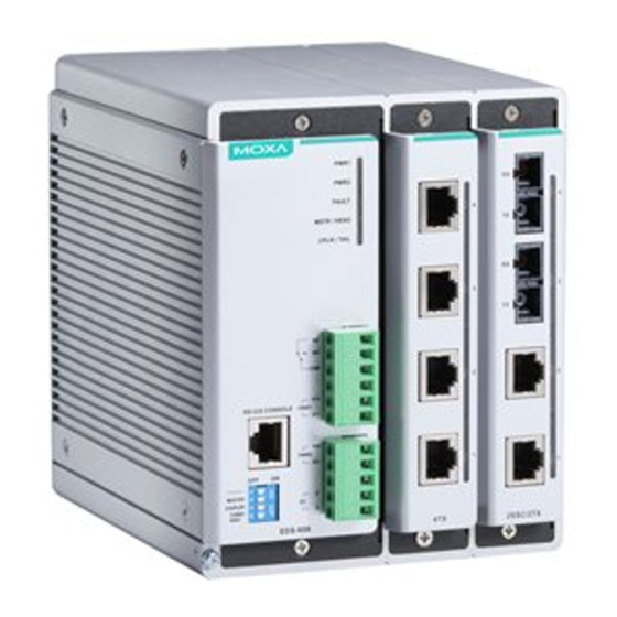
Package Checklist The Moxa EDS-600 Series is shipped with the following items. If any of these items is missing or damaged, please contact your customer service representative for assistance. • 1 EDS-600 EtherDevice Switch • RJ45 to DB9 console port cable •... - Page 3 Panel Views of the EDS-608 Front Panel: 1. System Status LEDs 2. Fast Ethernet Interface Module port LEDs 3. Fast Ethernet Interface Module 4. Terminal block for 2 power inputs, 1 DI/DO, and 1 relay output 5. Grounding screw 6. DIP switches for Ring Master, Ring Coupler, and Turbo Ring 7.
- Page 4 Panel Views of the EDS-611 Front Panel: 1. System Status LEDs 2. Fast Ethernet Interface Module port LEDs 3. Fast Ethernet Interface Module 4. Terminal block for 2 power inputs, 1 DI/DO, and 1 Relay output 5. Grounding screw 6. DIP switches for Ring Master, Ring Coupler, and Turbo Ring 7.
- Page 5 Panel Views of the EDS-616 Front Panel: 1. System Status LEDs 2. Fast Ethernet Interface Module port LEDs 3. Fast Ethernet Interface Module 4. Terminal block for 2 power inputs, 1 DI/DO, and 1 relay output 5. Grounding screw 6. DIP switches for Ring Master, Ring Coupler, and Turbo Ring 7.
- Page 6 Panel Views of the EDS-619 Front Panel: 1. System Status LEDs 2. Fast Ethernet Interface Module port LEDs 3. Fast Ethernet Interface Module 4. Terminal block for 2 power inputs, 1 DI/DO, and 1 relay output 5. Grounding screw 6. DIP switches for Ring Master, Ring Coupler, and Turbo Ring 7.
-
Page 7: Mounting Dimensions
Mounting Dimensions EDS-608/EDS-611 - 7 -... -
Page 8: Din-Rail Mounting
EDS-616/EDS-619 DIN-Rail Mounting The aluminum DIN-Rail attachment plate should already be fixed to the back panel of the EDS-600 when you take it out of the box. If you need to reattach the DIN-Rail attachment plate to the EDS-600, be sure the spring-loaded bracket is situated towards the bottom, as shown in the following figures. -
Page 9: Wall Mounting (Optional)
STEP 2: STEP 3: Insert the top of the DIN-Rail into The DIN-Rail attachment unit will the top slots on the DIN-Rail snap into place as shown in the attachment plate. following illustration. To remove the Moxa EDS-600 switch from the DIN-Rail, use a screwdriver to push down the spring-loaded bracket until it locks in place, as shown in the following diagram. -
Page 10: Atex Information
Do not screw the screws in all the way—leave about 2 mm to allow room for sliding the wall mount panel between the wall and the screws. STEP 3: Once the screws are fixed to the wall, insert the four screw heads through the wide parts of the keyhole-shaped apertures, and then slide the EDS-600 downwards, as indicated in the figure at the right. -
Page 11: Wiring Requirements
Wiring Requirements WARNING Do not disconnect modules or wires unless power has been switched off or the area is known to be non-hazardous. The devices may only be connected to the supply voltage shown on the type plate. The devices are designed for operation with a Safety Extra-Low Voltage. -
Page 12: Wiring The Relay Contact
ATTENTION This product is intended to be mounted to a well-grounded mounting surface such as a metal panel. Wiring the Relay Contact The EDS-600 has a set of relay outputs. The relay contact uses two of the terminal block’s contacts located on the EDS-600’s front panel. Refer to the next section for detailed instructions on how to connect the wires to the terminal block connector, and how to attach the terminal block connector to the terminal block receptor. -
Page 13: Wiring The Digital Inputs
STEP 1: Insert the negative/positive DC wires into the V-/V+ terminals, respectively. STEP 2: To keep the DC wires from pulling loose, use a small flat-blade screwdriver to tighten the wire-clamp screws on the front of the terminal block connector. STEP 3: Insert the plastic terminal block connector prongs into the terminal block receptor, which is... - Page 14 RS-232 Connection The EDS-600 has one RS-232 (10-pin RJ45) console port, located on the front panel. Use either an RJ45-to-DB9 (see the following cable wiring diagrams) to connect the EDS-600’s console port to your PC’s COM port. You may then use a console terminal program, such as Moxa PComm Terminal Emulator, to access the EDS-600’s console configuration utility.
- Page 15 10/100Base T(x) RJ45 Pinouts MDI Port Pinouts MDI-X Port Pinouts 8-pin RJ45 Signal Signal 1000BaseT RJ45 Pinouts MDI-X BI_DA+ BI_DB+ BI_DA- BI_DB- BI_DB+ BI_DA+ BI_DC+ BI_DD+ BI_DC- BI_DD- BI_DB- BI_DA- BI_DD+ BI_DC+ BI_DD- BI_DC- RJ45 (8-pin) to RJ45 (8-pin) Straight-Through Cable Wiring RJ45 (8-pin) to RJ45 (8-pin) Cross-Over Cable Wiring 100BaseFX or 1000BaseSFP Fiber Port The Gigabit Ethernet ports on the EDS-600 series are SFP slots, which...
-
Page 16: Turbo Ring Dip Switch Settings
The concept behind the LC port and cable is quite straightforward. Suppose you are connecting devices 1 and 2. Unlike electrical signals, optical signals do not require a circuit in order to transmit data. Consequently, one of the optical lines is used to transmit data from device 1 to device 2, and the other optical line is used to transmit data from device 2 to device 1, for full-duplex transmission. - Page 17 “Turbo Ring” DIP Switch Settings DIP 1 DIP 2 DIP 3 DIP 4 Reserved for ON: Enables this ON: Enables the ON: Activates future use. EDS as the Ring default “Ring DIP switches 1, 2, Master. Coupling” ports. 3 to configure “Turbo Ring”...
-
Page 18: Led Indicators
Since the maximum length of a category 5 twisted-pair cable is 100 meters, the cable length must be considered when designing a network that utilizes this function. For example, the total length of the cables from Switch A to C, or B to C must be no more than 100 meters. This way, if the two adjacent nodes (Switch B or C for example) encounter a power failure, there will be no stoppage, provided that the total length of the cables A-to-C, and B-to-D does not exceed 100 meters. -
Page 19: Specifications
Color State Description 10/100 Mbps link is active. Data is being transmitted at 10/100 AMBER Blinking Mbps. G1/G2/G3 (EDS-611/ 10/100 Mbps link is inactive. EDS-619 1000 Mbps link is active. only) Data is being transmitted at 1000 GREEN Blinking Mbps. 1000 Mbps link is inactive. - Page 20 EDS-619: 2.3 A Connection Two removable 5-pin and 6-pin terminal blocks Overload Current Present Protection Reverse Polarity Present Protection Mechanical Casing IP30 protection, metal case Dimensions (W × H × D) EDS-608/611: 125 x 151 x 157.4 mm (4.92 x 5.95 x 6.20 in) EDS-616/619: 185 x 151 x 157.4 mm (7.28 x 5.95 x 6.20 in)
Need help?
Do you have a question about the EtherDevice EDS-600 Series and is the answer not in the manual?
Questions and answers