
Related Manuals for Yetter 2967-006A


Summary of Contents for Yetter 2967-006A
- Page 1 2967-006A RESIDUE MANAGER FOR KINZE UNIT MOUNTED COULTER OPERATOR’S MANUAL 2565-962_REV_A • 06/2021 YETTER MANUFACTURING CO. FOUNDED 1930 Colchester, IL 62326-0358 Toll free: 800/447-5777 309/776-3222 (Fax) Website: www.yetterco.com E-mail: info@yetterco.com...
-
Page 2: Foreword
Important will WARRANTY Yetter Manufacturing warrants all products manufactured and sold by it against defects in material. This warranty being expressly limited to replacement at the factory of such parts or products as shall appear to be defective after inspection. - Page 3 SAFETY PRECAUTIONS A brief description of signal words that may be used in this manual: CAUTION: Used as a general reminder of good safety practices or to direct attention to unsafe practices. WARNING: Denotes a specific potential hazard. DANGER: Denotes the most serious specific potential hazard. CAUTION Consult your implement and tractor operator’s manual for correct and safe operating practices.
-
Page 4: Table Of Contents
Part Identification .......................... 20-25 BOLT TORQUE Before operating the 2967-006A Residue Manager for the first time, check to be sure that all hardware is tight. Check all hardware again after approximately 50 hours of operation and at the beginning of each planting season. -
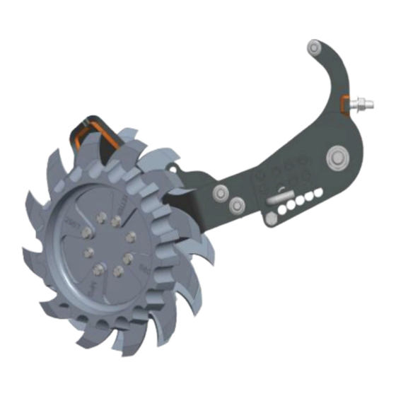
Page 5: Image Identifications
IMAGE IDENTIFICATION 2967-006A 2967-006A-FW... - Page 6 IMAGE IDENTIFICATION 2967-006A-BW 2967-006A-BW-FW...
- Page 7 IMAGE IDENTIFICATION 2967-006A-ST-FW...
-
Page 8: Assembly Instructions
ASSEMBLY INSTRUCTIONS STEP 1. Remove the bottom left hand bolt from the coulter. Install the 2966-297 mount bracket with the ½ X 2” cap screw, ½ flat washers and ½ locknut. - Page 9 ASSEMBLY INSTRUCTIONS STEP 1A. “CAST IRON COULTER” Remove the bottom left hand bolt from the coulter. Install the 2966-297 mount bracket with the ½” X 2-1/4 cap screw, ½” flat washers, 2966-298 adapter and ½” locknut.
- Page 10 ASSEMBLY INSTRUCTIONS STEP 2. Attach the 2966-295 combo arm to the coulter and 2966-297 mount bracket using the ¾” X 10” cap screw, ¾” flat washers, 2966-402 bushings, 2966-398 adjustment plate and ¾” locknut.
- Page 11 ASSEMBLY INSTRUCTIONS STEP 2A. Attach the 2966-295 combo arm to the coulter and 2966-297 mount bracket using the ¾” cap screws, ¾” flat washers, 2966-402 bushings and 2966-398 adjustment plate.
- Page 12 ASSEMBLY INSTRUCTIONS STEP 3. Attach 2966-398 adjustment plate to the 2966-297 mount bracket using the ½” x 2” cap screw and ½” locknut. DO NOT FULLY TIGHTEN UNTIL STEP 4.
- Page 13 ASSEMBLY INSTRUCTIONS STEP 4. Install the 2984-326 pin to align the adjustment holes of the 2966-295 combo arm, 2966-297 mount bracket and 2966-398 adjustment plate. NOW FULLY TIGHTEN THE ½” X 2” cap screw to secure the 2966-398 adjustment plate in position.
- Page 14 ASSEMBLY INSTRUCTIONS STEP 5. Attach the left hand, right hand wheel assemblies and scrapers to the combo arm. Secure with the 5/8 flange lock hex nuts.
- Page 15 ASSEMBLY INSTRUCTIONS STEP 6. OPTIONAL: Attach the 2966-405 cylinder anchor to the 2966-295 combo arm using the ½” carriage bolts, spacers and ½” flange lock nuts. Attach the air cylinder to the 2966-297 mount bracket using the 7/16” X 1-1/2” cap screw and 7/16”...
- Page 16 IMPORTANT: failure to properly set the planter frame height and levelness can result in less than successful operation of the planter and the Yetter product and may result in damaged equipment. All operators should read and thoroughly understand the instructions given prior to using the Yetter product.
- Page 17 PLANTER HEIGHT ADJUSTMENT Figure A. – The planter hitch and frame are both 20” off the ground. To ensure this, visually check to see that the planter boxes are level and that the planter unit parallel arms are also parallel with the ground. When using planter attachments located in front of the planter unit, this setting is very important.
-
Page 18: Operation
OPERATION CAUTION: Where rocks are present the residue manager should be set in the “float” position, not locked down. Adjust the residue manager to move crop residue aside and not move any soil. Adjustments to the residue manager may have to be made when changing field conditions and type and amount of residue. -
Page 19: Maintenance
Clean machine thoroughly to remove all dirt, debris, and crop residue, which would hold moisture and cause rusting. Inspect machine for worn or broken parts. See your Yetter Farm Equipment dealer during the off-season so that parts or service can be acquired when machine is not needed in the field. -
Page 20: Part Identification
PART IDENTIFICATION 2967-006A-ST-FW KINZE WELDED COULTER (NOT INCLUDED... - Page 21 PART IDENTIFICATION 2967-006A-ST-FW KINZE CAST COULTER (NOT INCLUDED)
- Page 22 PART IDENTIFICATION 2967-006A-ST-FW KINZE WELDED COULTER (NOT INCLUDED) PRESCISION CLEAN SWEEP AIR CYLINDER (NOT INCLUDED)
- Page 23 PART IDENTIFICATION 2967-006A-ST-FW KINZE CAST COULTER (NOT INCLUDED) PRESCISION CLEAN SWEEP AIR CYLINDER (NOT INCLUDED)
- Page 24 PART IDENTIFICATION 2966-140-ST-FW 2966-140-BW-FW...
- Page 25 PART IDENTIFICATION 2966-141-FW...
- Page 26 NOTES...
- Page 27 NOTES...
- Page 28 2565-962 02/2018...
Need help?
Do you have a question about the 2967-006A and is the answer not in the manual?
Questions and answers