Phoenix Contact Axioline F User Manual
Safety module with safe digital outputs
Hide thumbs
Also See for Axioline F:
- User manual (148 pages) ,
- User manual (44 pages) ,
- User manual (110 pages)

Subscribe to Our Youtube Channel
Related Manuals for Phoenix Contact Axioline F


Summary of Contents for Phoenix Contact Axioline F
- Page 1 Axioline F safety module with safe digital outputs User manual Arrow.com. Downloaded from...
- Page 2 User manual Axioline F safety module with safe digital outputs 2016-11-10 Designation: UM EN AXL F SSDO8/3 1F Revision: This user manual is valid for: Designation From HW/FW Order No. revision AXL F SSDO8/3 1F 01/220 2702264 PHOENIX CONTACT 106888_en_01 Arrow.com.
- Page 3 How to contact us Internet Up-to-date information on Phoenix Contact products and our Terms and Conditions can be found on the Internet at: phoenixcontact.com Make sure you always use the latest documentation.
- Page 4 The receipt of technical documentation (in particular user documentation) does not constitute any further duty on the part of Phoenix Contact to furnish information on modifications to products and/or technical documentation. You are responsible to verify the suitability and intended use of the products in your specific application, in particular with regard to observing the applicable standards and regulations.
-
Page 5: Table Of Contents
2.7.4 Parameterization errors ................ 20 Process data words ..................... 21 Programming data/configuration data..............23 Integration of the Axioline F local bus ..................25 Supply voltage of the module logic ..............25 Supply voltage U ....................26 DC distribution network according to IEC 61326-3-1 ........... 27 Terminal point assignment................... - Page 6 4.1.4 Mounting and removing the module ............. 31 Electrical installation .................... 33 4.2.1 Electrical installation of the Axioline F station ........33 4.2.2 Electrical installation of the module ............33 Parameterization of the module ....................35 Parameterization in a SafetyBridge system ............35 Parameterization of the safe outputs ..............
- Page 7 Appendix: checklists .........................69 Planning ...................... 70 Assembly and electrical installation ..............71 Startup and parameterization ................. 72 Validation ......................73 Appendix: index ........................75 Appendix: revision history......................77 106888_en_01 PHOENIX CONTACT Arrow.com. Arrow.com. Arrow.com. Arrow.com. Arrow.com. Arrow.com. Arrow.com. Downloaded from Downloaded from...
- Page 8 AXL F SSDO8/3 1F PHOENIX CONTACT 106888_en_01 Arrow.com. Arrow.com. Arrow.com. Arrow.com. Arrow.com. Arrow.com. Arrow.com. Arrow.com. Downloaded from Downloaded from Downloaded from Downloaded from Downloaded from Downloaded from Downloaded from Downloaded from...
-
Page 9: For Your Safety
– SafetyBridge system – Components used – Axioline F product range – Operation of the software tools – Safety regulations in the field of application In the context of the use of the system, the following operations must only be carried out by qualified personnel: –... -
Page 10: Electrical Safety
In this case, the correct operation of the safety module can no longer be ensured. In the event of an error, send the module to Phoenix Contact or contact Phoenix Contact immediately and engage a service engineer. -
Page 11: Safety Of The Machine Or System
Safe shutdown of contactors, motors (24 V DC), valves, ohmic, inductive, and capacitive loads The module is not suitable for applications in which stop category 1 also has to be observed in the event of an error. 106888_en_01 PHOENIX CONTACT Arrow.com. Arrow.com. Arrow.com. Arrow.com. -
Page 12: Documentation
For the SafetyBridge system function blocks Please also observe the information on the bus system used. Documentation for the Axioline F: system and installation user manual, UM EN AXL F SYS INST Axioline F product range Documentation for the bus coupler used... -
Page 13: Product Description
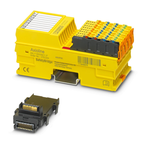
Product description Short description of the module The AXL F SSDO8/3 1F module is an output module for use at any point in an Axioline F station. The module is designed for use in the SafetyBridge system. The SafetyBridge address is set via a DIP switch. -
Page 14: Structure Of The Module
Diagnostics and status indicators DIP switch More detailed information on setting the switch: see Section 4.1.3 “Setting the DIP switch” on page 30. Housing dimensions 53,6 Figure 2-2 Housing dimensions (in mm) PHOENIX CONTACT 106888_en_01 Arrow.com. Arrow.com. Arrow.com. Arrow.com. Arrow.com. Arrow.com. -
Page 15: Safe Digital Outputs
These test pulses are visible at the output and can trigger undesirable reactions with quick responding actuators. The test pulses are either light pulses (brief activation) which can be disabled or dark pulses (brief deactivation) which cannot be disabled. 106888_en_01 PHOENIX CONTACT Arrow.com. Arrow.com. Arrow.com. Arrow.com. -
Page 16: Connection Options For Actuators Depending On The Parameterization
For connection example, see page * If the test pulses are disabled, a cross-circuit between the outputs is only detected if the output is enabled. To achieve Cat. 3, two-channel actuators are usually used. PHOENIX CONTACT 106888_en_01 Arrow.com. Arrow.com. Arrow.com. -
Page 17: Local Diagnostics And Status Indicators
(Only applies if UI is on or flashing at the same time.) Red on Hardware fault. Communication to the higher-level controller is disabled. The module has entered the safe state (failure state). Flashing red The module is not parameterized. 106888_en_01 PHOENIX CONTACT Arrow.com. Arrow.com. Arrow.com. Arrow.com. Arrow.com. Arrow.com. - Page 18 Green on Output at logic “1”. 10 - 17 Diagnostics for each output from 0 - 7 No error present at the output. Red on Error at the output (e.g., short circuit). PHOENIX CONTACT 106888_en_01 Arrow.com. Arrow.com. Arrow.com. Arrow.com. Arrow.com.
-
Page 19: Safe State
Section 6 “Connection examples for safe outputs” on page 39. If an error occurs on a channel of an output parameterized as “two-channel”, the other corresponding channel also enters the safe state. 106888_en_01 PHOENIX CONTACT Arrow.com. Arrow.com. Arrow.com. Arrow.com. -
Page 20: Device Errors
The module switches to the safe state following parameterization errors. The FS LED on the module flashes. In the event of faulty parameterization, a diagnostic message is transmitted to the logic module: see Section 8 “Errors: messages and removal” on page 53. PHOENIX CONTACT 106888_en_01 Arrow.com. Arrow.com. -
Page 21: Process Data Words
Product description Process data words The module occupies four words in the Axioline F system. Access the process data words via the “Operate” function block. The module has feedback data and enable data. Feedback data The bits in this register mirror the states of the digital outputs as diagnostic data. This data can be used if an output has been parameterized with a switch-off delay. - Page 22 AXL F SSDO8/3 1F; bit x See block description for the relevant controller. OUTx_Chy Safe output x, channel y Internal functionality that is enabled by means of parameterization; not visible in SAFECONF PHOENIX CONTACT 106888_en_01 Arrow.com. Arrow.com. Arrow.com. Arrow.com.
-
Page 23: Programming Data/Configuration Data
For two-channel parameterization, only use the process data bit of the first channel. Programming data/configuration data Phoenix Contact provides device description files for various control systems. The programming data/configuration data is defined in the device description (FDCML, GSD, GSDML, etc.) according to the bus or network used. - Page 24 AXL F SSDO8/3 1F PHOENIX CONTACT 106888_en_01 Arrow.com. Arrow.com. Arrow.com. Arrow.com. Arrow.com. Arrow.com. Arrow.com. Arrow.com. Arrow.com. Arrow.com. Arrow.com. Arrow.com. Arrow.com. Arrow.com. Arrow.com. Arrow.com. Arrow.com. Arrow.com. Arrow.com. Arrow.com. Arrow.com. Arrow.com. Arrow.com. Arrow.com. Downloaded from Downloaded from Downloaded from Downloaded from Downloaded from...
-
Page 25: Integration Of The Axioline F Local Bus
Integration of the Axioline F local bus The module is integrated for operation in an Axioline F station. More detailed information on the structure of an Axioline F station: see UM EN AXL F SYS INST user manual. Supply voltage of the module logic The supply voltage for the module logic is generated in the bus coupler and led to the Axioline F module via the bus base module. -
Page 26: Supply Voltage U O
24 V DC external fuse (PELV) 230 V or supply at the Axioline F module 24 V GND for supply at a bus coupler or a power terminal 105739B000_en Figure 3-1... -
Page 27: Dc Distribution Network According To Iec 61326-3-1
Terminal point assignment Figure 3-2 Terminal point assignment The Axioline F connectors are supplied with the module. They are color coded and marked for connection. Only use the connectors supplied with the module. The following applies for the tables below: –... - Page 28 Parasitic voltages can result in the loss of the safety function. • Connect the actuator ground to the ground terminal point of the corresponding output on the Axioline F connector. An external ground may not be used. PHOENIX CONTACT 106888_en_01 Arrow.com.
-
Page 29: Assembly, Removal, And Electrical Installation
• Before assembling or removing the module, disconnect the power to the module and the entire Axioline F station and make sure that the system cannot be switched on again. •... -
Page 30: Setting The Dip Switch
Remove the marking field and set the address in the switch below it. • Reattach the marking field to the module. The set address is only applied on power up. If the address is adjusted during operation, the module responds with a failure state. PHOENIX CONTACT 106888_en_01 Arrow.com. Arrow.com. Arrow.com. -
Page 31: Mounting And Removing The Module
(base latches) of the module one after the other to release it (A). • Remove the module perpendicular to the DIN rail (B). 106888_en_01 PHOENIX CONTACT Arrow.com. Arrow.com. Arrow.com. Arrow.com. Arrow.com. Arrow.com. - Page 32 Press firmly on the connector. Make sure that the locking latch snaps in. Remove • Release the locking latch (A). • Tilt the connector upwards slightly (B). • Remove the connector from the module (C). PHOENIX CONTACT 106888_en_01 Arrow.com. Arrow.com. Arrow.com. Arrow.com. Arrow.com. Arrow.com. Arrow.com.
-
Page 33: Electrical Installation
– Connecting the supply voltages for the Axioline F station • Carry out electrical installation for the Axioline F station according to the following user manuals: – Axioline F: system and installation user manual, UM EN AXL F SYS INST –... - Page 34 AXL F SSDO8/3 1F PHOENIX CONTACT 106888_en_01 Arrow.com. Arrow.com. Arrow.com. Arrow.com. Arrow.com. Arrow.com. Arrow.com. Arrow.com. Arrow.com. Arrow.com. Arrow.com. Arrow.com. Arrow.com. Arrow.com. Arrow.com. Arrow.com. Arrow.com. Arrow.com. Arrow.com. Arrow.com. Arrow.com. Arrow.com. Arrow.com. Arrow.com. Arrow.com. Arrow.com. Arrow.com. Arrow.com. Arrow.com. Arrow.com. Arrow.com. Arrow.com. Arrow.com.
-
Page 35: Parameterization Of The Module
In addition, the error is indicated at the controller. • In this case, check and correct the settings. Information on error messages and troubleshooting: see Section 8 “Errors: messages and removal” on page 53. 106888_en_01 PHOENIX CONTACT Arrow.com. Arrow.com. Arrow.com. Arrow.com. Arrow.com. -
Page 36: Parameterization Of The Safe Outputs
However, outputs parameterized as “Not used” are tested with test pulses. Observe the additional information: see “Requirements for actuators/controlled devices” on page 15, see Section 6 “Connection examples for safe outputs” on page 39. PHOENIX CONTACT 106888_en_01 Arrow.com. Arrow.com. -
Page 37: Behavior Of The Outputs In The Event Of Enabled Switch-Off Delay For Stop Category 1
WARNING: Incorrect/insufficient safety distances Selecting the wrong switch-off delay can result in incorrect safety distances being designed. • When designing the safety distances, take the selected switch-off delay into consideration. 106888_en_01 PHOENIX CONTACT Arrow.com. Arrow.com. Arrow.com. Arrow.com. Arrow.com. Arrow.com. Arrow.com. - Page 38 AXL F SSDO8/3 1F PHOENIX CONTACT 106888_en_01 Arrow.com. Arrow.com. Arrow.com. Arrow.com. Arrow.com. Arrow.com. Arrow.com. Arrow.com. Arrow.com. Arrow.com. Arrow.com. Arrow.com. Arrow.com. Arrow.com. Arrow.com. Arrow.com. Arrow.com. Arrow.com. Arrow.com. Arrow.com. Arrow.com. Arrow.com. Arrow.com. Arrow.com. Arrow.com. Arrow.com. Arrow.com. Arrow.com. Arrow.com. Arrow.com. Arrow.com. Arrow.com. Arrow.com.
-
Page 39: Connection Examples For Safe Outputs
The examples only describe the options for the electrical connection of controlled devices/actuators to the safe outputs. Should you have any questions regarding your applications, please contact the Phoenix Contact safety hotline: see Section 1.8 “Safety hotline” on page 12. The following are specified for each example: 106888_en_01 PHOENIX CONTACT Arrow.com. - Page 40 Only errors between outputs, which are on the same connector, are described. For example, in the event of correct installation, cross-circuits with outputs of other connectors cannot occur. PHOENIX CONTACT 106888_en_01 Arrow.com. Arrow.com. Arrow.com.
-
Page 41: Notes On The Protective Circuit Of External Relays/Contactors (Freewheeling Circuit)
SIL 2/SILCL 2 1% of 10 1% of 10 SIL 3/SILCL 3 1% of 10 1% of 10 Performance level Use standard EN ISO 13849-1 to determine the performance level. 106888_en_01 PHOENIX CONTACT Arrow.com. Arrow.com. Arrow.com. Arrow.com. Arrow.com. Arrow.com. Arrow.com. Arrow.com. - Page 42 An accumulation of errors must not result in the loss of the safety function. Following the third error, evaluation can be aborted if the probability of further errors occurring is low. PHOENIX CONTACT 106888_en_01 Arrow.com. Arrow.com.
-
Page 43: Single-Channel Assignment Of Safe Outputs
Parasitic voltages can result in the loss of the safety function. • Connect the actuator ground to the ground terminal point of the corresponding output on the Axioline F connector. An external ground may not be used. Basic specifications Actuator... - Page 44 Enabled Or disabled (in software: test impulses (output switched off)) Switch-off delay for stop Enabled Or disabled category 1 Output Single-channel Enable Enabled Or disabled PHOENIX CONTACT 106888_en_01 Arrow.com. Arrow.com. Arrow.com. Arrow.com. Arrow.com. Arrow.com. Arrow.com. Arrow.com. Arrow.com. Arrow.com. Arrow.com. Arrow.com.
-
Page 45: Two-Channel Assignment Of Safe Outputs
• Connect the actuator ground to the ground terminal point of the corresponding output on the Axioline F connector. An external ground may not be used. The failure detection time does not have to be taken into consideration for two-channel assignment. - Page 46 This can result in unexpected machine startup. • Before acknowledging an error, make sure that no persons can access the danger zone. SF = safety function OUTx = diagnostic message (LED) for each output X PHOENIX CONTACT 106888_en_01 Arrow.com. Arrow.com. Arrow.com. Arrow.com. Arrow.com. Arrow.com.
- Page 47 (in software: test impulses (output switched off)) Switch-off delay for stop Enabled Enabled Or disabled category 1 Output Two-channel Two-channel Enable Enabled Enabled Or disabled 106888_en_01 PHOENIX CONTACT Arrow.com. Arrow.com. Arrow.com. Arrow.com. Arrow.com. Arrow.com. Arrow.com. Arrow.com. Arrow.com. Arrow.com. Arrow.com. Arrow.com. Arrow.com. Arrow.com.
- Page 48 AXL F SSDO8/3 1F PHOENIX CONTACT 106888_en_01 Arrow.com. Arrow.com. Arrow.com. Arrow.com. Arrow.com. Arrow.com. Arrow.com. Arrow.com. Arrow.com. Arrow.com. Arrow.com. Arrow.com. Arrow.com. Arrow.com. Arrow.com. Arrow.com. Arrow.com. Arrow.com. Arrow.com. Arrow.com. Arrow.com. Arrow.com. Arrow.com. Arrow.com. Arrow.com. Arrow.com. Arrow.com. Arrow.com. Arrow.com. Arrow.com. Arrow.com. Arrow.com. Arrow.com.
-
Page 49: Startup And Validation
– Make sure that functional earth ground is connected. Connect the necessary voltages to the Axioline F station. UM EN AXL SYS INST user manual or documentation for the module Connect the necessary voltages (U ) to the module. -
Page 50: Startup Mode
In the Startup+ software, enter the address set on the device. For additional information on the Startup+ software, refer to the documentation for the software. The software can be downloaded free of charge at phoenixcontact.net/products. PHOENIX CONTACT 106888_en_01 Arrow.com. Arrow.com. -
Page 51: Restart After Replacing A Module
• Before assembling or removing the module, disconnect the power to the module and the entire Axioline F station and make sure that the system cannot be switched on again. •... - Page 52 AXL F SSDO8/3 1F PHOENIX CONTACT 106888_en_01 Arrow.com. Arrow.com. Arrow.com. Arrow.com. Arrow.com. Arrow.com. Arrow.com. Arrow.com. Arrow.com. Arrow.com. Arrow.com. Arrow.com. Arrow.com. Arrow.com. Arrow.com. Arrow.com. Arrow.com. Arrow.com. Arrow.com. Arrow.com. Arrow.com. Arrow.com. Arrow.com. Arrow.com. Arrow.com. Arrow.com. Arrow.com. Arrow.com. Arrow.com. Arrow.com. Arrow.com. Arrow.com. Arrow.com.
-
Page 53: Errors: Messages And Removal
Module replacement following an error If the safety module is replaced in the event of an error, proceed as described in “Assembly, removal, and electrical installation” on page 29 and “Restart” on page 51. 106888_en_01 PHOENIX CONTACT Arrow.com. Arrow.com. Arrow.com. -
Page 54: Note About The Error Codes
4021: no error; the SafetyBridge address is displayed The error codes are listed in ascending order in Table 8-2 “Error codes”. If error codes are indicated by the system which do not appear in the table, please contact Phoenix Contact. PHOENIX CONTACT 106888_en_01 Arrow.com. -
Page 55: Error Codes
free selftest. The states 005A OUT2_Ch2 external wiring at the outputs are 005B OUT3_Ch2 transmitted immediately. If the error occurs permanently: Replace module 106888_en_01 PHOENIX CONTACT Arrow.com. Arrow.com. Arrow.com. Arrow.com. Arrow.com. Arrow.com. Arrow.com. Arrow.com. Arrow.com. Arrow.com. Arrow.com. Arrow.com. Arrow.com. - Page 56 Replace module Acknowledgment: Acknowledgment triggers the message and results in a restart following an error- free selftest. The states at the outputs are transmitted immediately. PHOENIX CONTACT 106888_en_01 Arrow.com. Arrow.com. Arrow.com. Arrow.com. Arrow.com. Arrow.com. Arrow.com. Arrow.com. Arrow.com.
- Page 57 Resend parameter data 02C2 OUT2_Ch1&2 “Assignment of the to the module 02C3 OUT3_Ch1&2 outputs” (deactivate/activate parameterization “Operate” block) Acknowledgment: not possible 106888_en_01 PHOENIX CONTACT Arrow.com. Arrow.com. Arrow.com. Arrow.com. Arrow.com. Arrow.com. Arrow.com. Arrow.com. Arrow.com. Arrow.com. Arrow.com. Arrow.com. Arrow.com. Arrow.com.
- Page 58 Parameter data record does not match the Check assignment of device process data at the “Operate” block Resend parameter data to the module (deactivate/activate “Operate” block) Acknowledgment: not possible PHOENIX CONTACT 106888_en_01 Arrow.com. Arrow.com. Arrow.com. Arrow.com. Arrow.com. Arrow.com. Arrow.com. Arrow.com. Arrow.com. Arrow.com.
- Page 59 Acknowledgment: not address set on the possible safety module 0441 SD on Internal error Module is in the safe state Please contact Phoenix Contact. 0446 Acknowledgment: not possible 0447 SD on Incorrect configuration Module is in the safe state 1.
- Page 60 AXL F SSDO8/3 1F Table 8-2 Error codes Error Error Error cause Effect Solution code location Error description Acknowledgment (hex) 8000 P on No error PHOENIX CONTACT 106888_en_01 Arrow.com. Arrow.com. Arrow.com. Arrow.com. Arrow.com. Arrow.com. Arrow.com. Arrow.com. Arrow.com. Arrow.com. Arrow.com. Arrow.com. Arrow.com. Arrow.com.
-
Page 61: Maintenance, Repair, Decommissioning, And Disposal
In this case, the correct operation of the safety module can no longer be ensured. • In the event of an error, send the module to Phoenix Contact or contact Phoenix Contact immediately and engage a service engineer. Decommissioning and disposal Carry out decommissioning according to the requirements of the machine or system manufacturer. - Page 62 AXL F SSDO8/3 1F PHOENIX CONTACT 106888_en_01 Arrow.com. Arrow.com. Arrow.com. Arrow.com. Arrow.com. Arrow.com. Arrow.com. Arrow.com. Arrow.com. Arrow.com. Arrow.com. Arrow.com. Arrow.com. Arrow.com. Arrow.com. Arrow.com. Arrow.com. Arrow.com. Arrow.com. Arrow.com. Arrow.com. Arrow.com. Arrow.com. Arrow.com. Arrow.com. Arrow.com. Arrow.com. Arrow.com. Arrow.com. Arrow.com. Arrow.com. Arrow.com. Arrow.com.
-
Page 63: 10 Technical Data And Ordering Data
Not resistant to gas that may endanger functions (sulfur dioxide (SO DIN 40046-37 hydrogen sulfide (H Resistance of the housing material to fungal decay Resistant Ambient compatibility Not resistant to organic chlorine compounds 106888_en_01 PHOENIX CONTACT Arrow.com. Arrow.com. Arrow.com. Arrow.com. Arrow.com. Arrow.com. Arrow.com. - Page 64 AXL F SSDO8/3 1F General data [...] Connection data for Axioline F connectors Connection method Spring-cage terminal blocks Conductor cross section Solid: 0.5 mm to 1.5 mm Flexible without sleeve: 0.25 mm to 1.5 mm Flexible with sleeve: 0.25 mm to 1.5 mm...
- Page 65 Safe digital outputs Quantity 4 two-channel or 8 single-channel (positive switching) Supply From supply voltage U Maximum output current per output (channel) 1.5 A (from 45°C according to CUL 106888_en_01 PHOENIX CONTACT Arrow.com. Arrow.com. Arrow.com. Arrow.com. Arrow.com. Arrow.com. Arrow.com. Arrow.com.
- Page 66 Please note that the load on a switch-on pulse (light test) of 1 ms must not fail or respond in a safety-critical way. • Please take this into consideration when selecting the actuator. Maximum duration of the test pulses (when switched on) 3 ms (depending on the load capacity) PHOENIX CONTACT 106888_en_01 Arrow.com. Arrow.com. Arrow.com.
-
Page 67: Conformance With Emc Directive
WARNING: Loss of safety function Parasitic voltages can result in the loss of the safety function. • Connect the actuator ground to the ground terminal point of the corresponding output on the Axioline F connector. An external ground may not be used. •... -
Page 68: Ordering Data: Module
Axioline F: diagnostic registers and error messages SafetyBridge User manual: UM EN AXL F LPSDO8/3 1F 2702171 Axioline F module with integrated safety logic and safe digital outputs SafetyBridge technology integration package for controllers from SBT_V3_PLC_Integration_Packages_1.8.exe 2702171 Phoenix Contact, Rockwell and Siemens (S7-1200 as of CPU 1214C, S7-1500, S7-300), Schneider as well as CODESYS-based controllers. -
Page 69: A Appendix: Checklists
These requirements must be met for a safety application, in order to complete the relevant phase using the checklist. Requirement (optional) These requirements are optional. For points that are not met, please enter an appropriate comment in the relevant field. 106888_en_01 PHOENIX CONTACT Arrow.com. Arrow.com. Arrow.com. Arrow.com. Arrow.com. -
Page 70: A 1 Planning
16 Have specifications for assembly and electrical installation been defined (e.g., EPLAN) and communicated to the relevant personnel? 17 Have specifications for startup been defined and communicated to the relevant personnel? Date Signature (editor) Date Signature (test engineer) PHOENIX CONTACT 106888_en_01 Arrow.com. Arrow.com. Arrow.com. Arrow.com. Arrow.com. Arrow.com. -
Page 71: A 2 Assembly And Electrical Installation
4 Does the connection technology correspond to the specifications in the technical data and in the relevant user manual? 5 Is the address switch set correctly according to the specifications? Date Signature (editor) Date Signature (test engineer) 106888_en_01 PHOENIX CONTACT Arrow.com. Arrow.com. Arrow.com. Arrow.com. Arrow.com. Arrow.com. Arrow.com. -
Page 72: A 3 Startup And Parameterization
No. Requirement (optional) No Comment 7 Have safety distances that must be observed been calculated according to the response and delay times implemented? Date Signature (editor) Date Signature (test engineer) PHOENIX CONTACT 106888_en_01 Arrow.com. Arrow.com. Arrow.com. Arrow.com. Arrow.com. Arrow.com. Arrow.com. -
Page 73: A 4 Validation
PELV? 10 Has the power supply of U and U in the Axioline F system from a power supply unit been implemented? 11 Is external protection of the module implemented (according to the specifications in this user manual for supply voltage U... - Page 74 AXL F SSDO8/3 1F PHOENIX CONTACT 106888_en_01 Arrow.com. Arrow.com. Arrow.com. Arrow.com. Arrow.com. Arrow.com. Arrow.com. Arrow.com. Arrow.com. Arrow.com. Arrow.com. Arrow.com. Arrow.com. Arrow.com. Arrow.com. Arrow.com. Arrow.com. Arrow.com. Arrow.com. Arrow.com. Arrow.com. Arrow.com. Arrow.com. Arrow.com. Arrow.com. Arrow.com. Arrow.com. Arrow.com. Arrow.com. Arrow.com. Arrow.com. Arrow.com. Arrow.com.
-
Page 75: B Appendix: Index
Directives ..............11 Positive switching........... 15 Disposal ...............61 Requirements for actuators ........15 Documentation, latest ..........12 Single-channel assignment ........15 Two-channel assignment ........15 Enable................21 Errors Acknowledgment............53 106888_en_01 PHOENIX CONTACT Arrow.com. Arrow.com. Arrow.com. Arrow.com. Arrow.com. Arrow.com. Arrow.com. Arrow.com. Arrow.com. Arrow.com. Arrow.com. - Page 76 SafetyBridge Address ..............35 Standards ..............11 Startup .................49 Startup mode ...............50 Status indicators ............17 Stop category 1............37 Supply voltage UO................26 Test pulses............. 15, 36 Transmission speed Setting ..............30 PHOENIX CONTACT 106888_en_01 Arrow.com. Arrow.com. Arrow.com. Arrow.com. Arrow.com. Arrow.com. Arrow.com. Arrow.com. Arrow.com. Arrow.com.
-
Page 77: C Appendix: Revision History
Appendix: revision history C Appendix: revision history Revision Date Contents 2016-03-22 First publication 2016-11-10 HW/FW revision updated page 2 EMC Directive updated page 67 106888_en_01 PHOENIX CONTACT Arrow.com. Arrow.com. Arrow.com. Arrow.com. Arrow.com. Arrow.com. Arrow.com. Arrow.com. Arrow.com. Arrow.com. Arrow.com. Arrow.com. Arrow.com. - Page 78 AXL F SSDO8/3 1F PHOENIX CONTACT 106888_en_01 Arrow.com. Arrow.com. Arrow.com. Arrow.com. Arrow.com. Arrow.com. Arrow.com. Arrow.com. Arrow.com. Arrow.com. Arrow.com. Arrow.com. Arrow.com. Arrow.com. Arrow.com. Arrow.com. Arrow.com. Arrow.com. Arrow.com. Arrow.com. Arrow.com. Arrow.com. Arrow.com. Arrow.com. Arrow.com. Arrow.com. Arrow.com. Arrow.com. Arrow.com. Arrow.com. Arrow.com. Arrow.com. Arrow.com.
Need help?
Do you have a question about the Axioline F and is the answer not in the manual?
Questions and answers