
Related Manuals for Phoenix Contact IB IL 24 PSDI 8-PAC


Summary of Contents for Phoenix Contact IB IL 24 PSDI 8-PAC
- Page 1 DOWNLOADED FROM WWW.SCATTS.CO.UK IB IL 24 PSDI 8-PAC Inline module with safe digital inputs User manual DOWNLOADED FROM WWW.SCATTS.CO.UK...
- Page 2 UM EN IB IL 24 PSDI 8-PAC, revision 07 2017-11-29 This user manual is valid for: Designation Revision Order No. as of HW/FW IB IL 24 PSDI 8-PAC 00/201 2985688 PHOENIX CONTACT GmbH & Co. KG • Flachsmarktstraße 8 • 32825 Blomberg • Germany phoenixcontact.com DOWNLOADED FROM WWW.SCATTS.CO.UK...
-
Page 3: Table Of Contents
Other bus systems (PROFIBUS, PROFINET, etc.) ......30 Inline potential and data routing, and Inline connectors ............31 Inline potential and data routing................31 Supply voltage U ....................31 Supply voltage U ....................32 Terminal point assignment................... 34 3 / 154 7602_en_07 PHOENIX CONTACT DOWNLOADED FROM WWW.SCATTS.CO.UK... - Page 4 DOWNLOADED FROM WWW.SCATTS.CO.UK IB IL 24 PSDI 8-PAC Assembly, removal, and electrical installation................37 Assembly and removal ..................37 4.1.1 Unpacking the module ................. 37 4.1.2 General ....................37 4.1.3 Setting the DIP switches ..............38 4.1.4 Assembly and removal of the safety module ........41 Electrical installation ....................
- Page 5 10 Maintenance, repair, decommissioning, and disposal ............123 10.1 Maintenance...................... 123 10.2 Repair........................ 123 10.3 Decommissioning and disposal ................. 123 11 Technical data and ordering data ...................125 11.1 System data ...................... 125 5 / 154 7602_en_07 PHOENIX CONTACT DOWNLOADED FROM WWW.SCATTS.CO.UK...
- Page 6 IB IL 24 PSDI 8-PAC 11.1.1 INTERBUS-Safety ................125 11.1.2 SafetyBridge ..................125 11.1.3 PROFIsafe ..................125 11.2 IB IL 24 PSDI 8-PAC..................126 11.3 Conformance with EMC Directive..............131 11.4 Ordering data ....................132 11.4.1 Ordering data: Safety module ............132 11.4.2 Ordering data: Accessories ...............
-
Page 7: For Your Safety
– Qualified application programmers and software engineers. The users must be familiar with the relevant safety concepts of automation technology as well as applicable stan- dards and other regulations. 7 / 154 7602_en_07 PHOENIX CONTACT DOWNLOADED FROM WWW.SCATTS.CO.UK... -
Page 8: General Safety Notes
DOWNLOADED FROM WWW.SCATTS.CO.UK IB IL 24 PSDI 8-PAC General safety notes WARNING: Depending on the application, incorrect handling of the safety module can pose serious risks for the user When working with the safety module within the INTERBUS-Safety-, SafetyBridge- or PROFIsafe system, please observe all safety notes included in this section. - Page 9 Repair work may not be carried out on the safety module. repairs In the event that an error cannot be removed, please contact Phoenix Contact immediately, engage a service engineer, or send the faulty module directly to Phoenix Contact. Do not open the housing It is strictly prohibited to open the housing.
-
Page 10: Electrical Safety
When selecting the equipment, please take into consideration the dirt and surge voltages which may occur during operation. The IB IL 24 PSDI 8-PAC module is designed for overvoltage category II (according to DIN EN 60664-1). If you expect surge voltages in the system, which exceed the values defined in overvoltage category II, take into consideration additional measures for voltage limitation. -
Page 11: Safety Of The Machine Or System
The safe devices are connected to the correct safe sensors and actuators – The safe input and output devices have been parameterized correctly – The variables have been linked to the safe sensors and actuators correctly (single- channel or two-channel) 11 / 154 7602_en_07 PHOENIX CONTACT DOWNLOADED FROM WWW.SCATTS.CO.UK... -
Page 12: Directives And Standards
Directives and standards The manufacturers and operators of machines and systems, in which the IB IL 24 PSDI 8-PAC module is used, are responsible for adhering to all applicable direc- tives and legislation. For the standards observed by the module, please refer to the certificate issued by the approval body and the EC declaration of conformity. -
Page 13: Documentation
For the safe controller used – For PROFIsafe I/O modules – For PROFIsafe function blocks Please also observe the relevant information about PROFIBUS, PROFINET and PROFIs- afe, which is available on the Internet at profisafe.net. 13 / 154 7602_en_07 PHOENIX CONTACT DOWNLOADED FROM WWW.SCATTS.CO.UK... - Page 14 DOWNLOADED FROM WWW.SCATTS.CO.UK IB IL 24 PSDI 8-PAC Standard INTERBUS When working on the INTERBUS system and its components, you must always keep the listed user manuals and other items of product documentation to hand and observe the infor- mation therein.
-
Page 15: Abbreviations Used
For terms and abbreviations used for PROFIsafe, please refer to “Appendix: PROFIsafe terms used in the user manual” on page 135. 1.10 Safety hotline Should you have any technical questions, please contact our 24-hour hotline. Phone: +49 5281 9462777 E-mail: safety-service@phoenixcontact.com 15 / 154 7602_en_07 PHOENIX CONTACT DOWNLOADED FROM WWW.SCATTS.CO.UK... - Page 16 DOWNLOADED FROM WWW.SCATTS.CO.UK IB IL 24 PSDI 8-PAC 16 / 154 PHOENIX CONTACT 7602_en_07 DOWNLOADED FROM WWW.SCATTS.CO.UK...
-
Page 17: Product Description
The IB IL 24 PSDI 8-PAC module is an input module that is designed for use within an Inline station. The IB IL 24 PSDI 8-PAC safety module can be used as part of an Inline station at any point within an INTERBUS-Safety, SafetyBridge or PROFIsafe system. -
Page 18: Structure Of The Safety Module
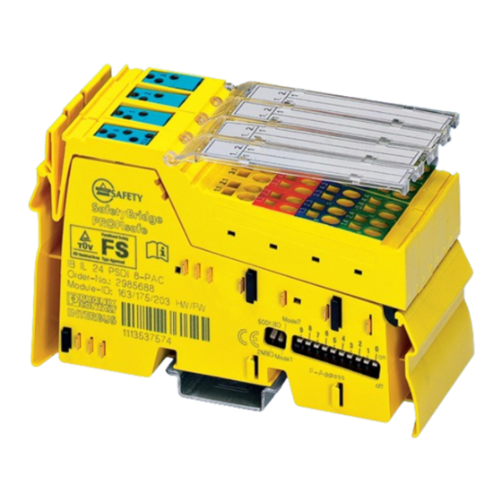
DOWNLOADED FROM WWW.SCATTS.CO.UK IB IL 24 PSDI 8-PAC Structure of the safety module U T 1 U T 2 D I8 76020002 Figure 2-1 Structure of the safety module Data jumpers (local bus) Electronics base with labeling including hardware/firmware version designation... -
Page 19: Housing Dimensions
DOWNLOADED FROM WWW.SCATTS.CO.UK Product description Housing dimensions 48.8 76022010 Figure 2-2 Housing dimensions (in mm) 19 / 154 7602_en_07 PHOENIX CONTACT DOWNLOADED FROM WWW.SCATTS.CO.UK... -
Page 20: Safe Digital Inputs And Clock Outputs Ut1 And Ut2
DOWNLOADED FROM WWW.SCATTS.CO.UK IB IL 24 PSDI 8-PAC Safe digital inputs and clock outputs UT1 and UT2 2.4.1 Safe digital inputs The safety module has four safe digital inputs for two-channel assignment or eight safe dig- ital inputs for single-channel assignment. The supply voltage for the inputs can be provided externally or via the clock outputs. - Page 21 – Please observe the applicable C standards in your application (e.g., EN 1010), in which, for example, the number of controlling devices required to achieve a particular category is specified. 21 / 154 7602_en_07 PHOENIX CONTACT DOWNLOADED FROM WWW.SCATTS.CO.UK...
-
Page 22: Clock Outputs Ut1 And Ut2
DOWNLOADED FROM WWW.SCATTS.CO.UK IB IL 24 PSDI 8-PAC 2.4.2 Clock outputs UT1 and UT2 The module has two independent clock outputs. They provide the supply voltage for the safe inputs. Each of these clock outputs can provide a pulse pattern to detect cross circuits and short circuits in the external wiring of the inputs. -
Page 23: Connection Options For Sensors Depending On The Parameterization
PL e PL d For connection example, see page Key: Cat. 3 can only be achieved with a redundant sensor. The category that can be achieved depends on the sensor used. 23 / 154 7602_en_07 PHOENIX CONTACT DOWNLOADED FROM WWW.SCATTS.CO.UK... -
Page 24: Local Diagnostic And Status Indicators
Local diagnostic and status indicators PSDI8 U T 1 U T 2 D I8 76020003 Figure 2-3 Local diagnostic and status indicators on the IB IL 24 PSDI 8-PAC module 24 / 154 PHOENIX CONTACT 7602_en_07 DOWNLOADED FROM WWW.SCATTS.CO.UK... - Page 25 Input at logic 1 Off: Input at logic 0 Even when the module is not parameterized, the physical state at the inputs is indicated. However, substitute value “0” is transmitted to the safe controller. 25 / 154 7602_en_07 PHOENIX CONTACT DOWNLOADED FROM WWW.SCATTS.CO.UK...
-
Page 26: Safe State
DOWNLOADED FROM WWW.SCATTS.CO.UK IB IL 24 PSDI 8-PAC Safe state The safe state for the module is the transmission of the value equal to “0” in the image of the inputs to the safe controller (INTERBUS-Safety, PROFIsafe) or the configurable safety mod- ule (SafetyBridge). -
Page 27: Device Errors
In the event of faulty parameterization, the relevant diagnostic message is transmitted to the safe controller (INTERBUS-Safety, PROFIsafe) or the configurable safety module (SafetyBridge) (see Section “Parameterization errors” on page 116). 27 / 154 7602_en_07 PHOENIX CONTACT DOWNLOADED FROM WWW.SCATTS.CO.UK... -
Page 28: Process Data Words
DOWNLOADED FROM WWW.SCATTS.CO.UK IB IL 24 PSDI 8-PAC Process data words 2.8.1 INTERBUS The module occupies three words in the INTERBUS system. In the standard control system, the input data is mapped to a single word. The input data can only be accessed via the safe INTERBUS controller. The safe INTERBUS controller provides the input data for the standard control system as standard data. -
Page 29: Profisafe (Profibus, Profinet)
The way in which these words are mapped in the higher-level control system is specific to the controller used and is described in the quick start guide for the controller. 29 / 154 7602_en_07 PHOENIX CONTACT DOWNLOADED FROM WWW.SCATTS.CO.UK... -
Page 30: Programming Data / Configuration Data
DOWNLOADED FROM WWW.SCATTS.CO.UK IB IL 24 PSDI 8-PAC Programming data / Configuration data 2.9.1 Local bus (INTERBUS) Protocol INTERBUS-Safety SafetyBridge PROFIsafe Protocol/address switch ..FF Any, determined by the configu- ..3FE rable safety module Operating mode Mode 1 Mode 2... -
Page 31: Inline Potential And Data Routing, And Inline Connectors
The maximum current carrying capacity for the supply voltage U is 2 A. This current carrying capacity can be reduced if certain terminals are used. Please refer to the information in the terminal-specific data sheets. 31 / 154 7602_en_07 PHOENIX CONTACT DOWNLOADED FROM WWW.SCATTS.CO.UK... -
Page 32: Supply Voltage U M
DOWNLOADED FROM WWW.SCATTS.CO.UK IB IL 24 PSDI 8-PAC Supply voltage U Supply the supply voltage at a bus coupler or a power terminal. It is supplied to the safety module vial the Inline potential jumper U WARNING: Loss of the safety function when using unsuitable power supplies Please observe the points in Section “Electrical safety”... - Page 33 DC distribution network. For devices that are intended for a typical sys- tem or machine distribution, the DC connections are viewed and tested as I/O signals according to IEC 61326-3-1. 33 / 154 7602_en_07 PHOENIX CONTACT DOWNLOADED FROM WWW.SCATTS.CO.UK...
-
Page 34: Terminal Point Assignment
DOWNLOADED FROM WWW.SCATTS.CO.UK IB IL 24 PSDI 8-PAC Terminal point assignment 73410004 Figure 3-2 Terminal point assignment The Inline connectors are supplied with the module. They are coded and marked accord- ingly for connection to prevent polarity reversal. Only use the connectors supplied with the module. - Page 35 Channel 1 and channel 2 WARNING: Loss of functional safety due to parasitic voltages For sensors that require a GND, these must be wired to 0 V (GND) on the module. 35 / 154 7602_en_07 PHOENIX CONTACT DOWNLOADED FROM WWW.SCATTS.CO.UK...
- Page 36 DOWNLOADED FROM WWW.SCATTS.CO.UK IB IL 24 PSDI 8-PAC 36 / 154 PHOENIX CONTACT 7602_en_07 DOWNLOADED FROM WWW.SCATTS.CO.UK...
-
Page 37: Assembly, Removal, And Electrical Installation
The system must only be started when neither the station nor the system can cause any damage. The IB IL 24 PSDI 8-PAC safety terminal is designed for use within an Inline station. Only use the safety terminal in the 24 V DC area of an Inline station. -
Page 38: Setting The Dip Switches
DOWNLOADED FROM WWW.SCATTS.CO.UK IB IL 24 PSDI 8-PAC 4.1.3 Setting the DIP switches Set the DIP switches before assembling the module in the Inline station. The switches cannot be accessed when the safety module is installed in the Inline station. - Page 39 Set the PROFIsafe address for the PROFIsafe device. PROFIsafe addresses 1 to 1022 (1 to 3FE ) are permitted. PROFIsafe switch position Table 4-2 Switch position for PROFIsafe PROFIsafe Mode switch Address switch Mode 1 to 3FE 39 / 154 7602_en_07 PHOENIX CONTACT DOWNLOADED FROM WWW.SCATTS.CO.UK...
- Page 40 DOWNLOADED FROM WWW.SCATTS.CO.UK IB IL 24 PSDI 8-PAC SafetyBridge WARNING: Loss of safety function during mixed operation During mixed operation between SafetyBridge V1 and/or SafetyBridge V2 with SafetyBridge V3, incorrect addressing may lead to a loss of the safety function.
-
Page 41: Assembly And Removal Of The Safety Module
Ensure that all featherkeys and keyways on adjacent terminals are securely interlocked. Figure 4-2 Snapping on the safety module base • Check that all the snap-on mechanisms are securely snapped into place. 41 / 154 7602_en_07 PHOENIX CONTACT DOWNLOADED FROM WWW.SCATTS.CO.UK... - Page 42 DOWNLOADED FROM WWW.SCATTS.CO.UK IB IL 24 PSDI 8-PAC – Insert plugs • Insert the plugs in the specified order (A, B). Only use the plugs supplied with the module. Figure 4-3 Inserting the plugs Removal • Disconnect the power to the station.
-
Page 43: Electrical Installation
Push a screwdriver into the slot of the appropriate terminal point (Figure 4-6, detail 1), so that you can insert the wire into the spring opening. Phoenix Contact recommends the screwdriver SZF 1 - 0.6X3.5 (Order No. 1204517; see Phoenix Contact “CLIPLINE” catalog). - Page 44 DOWNLOADED FROM WWW.SCATTS.CO.UK IB IL 24 PSDI 8-PAC 6 4 5 2 B 0 3 2 Figure 4-6 Connecting unshielded cables • Insert the assembled plugs in the corresponding module slot (see Section “Terminal point assignment” on page 34). •...
-
Page 45: Parameterization Of The Safety Module
The invalidity of the parameterization is indicated on the module by the flashing FS LED. In addition, errors are indicated at the safe INTERBUS controller. In this case, check and cor- rect the settings. 45 / 154 7602_en_07 PHOENIX CONTACT DOWNLOADED FROM WWW.SCATTS.CO.UK... -
Page 46: Parameterization In A Safetybridge System
It is assigned in the configuration software for the assigned configurable safety module. The address of the connected satellites (here: IB IL 24 PSDI 8-PAC) is based on the island number of the configurable safety module and the position in the bus navigator of the soft- ware tool. -
Page 47: Parameterization In A Profisafe System
Section “Errors: messages and removal” on page 111. F-Parameters and Assign the parameterizable F-Parameters and iParameters. For an overview of the module iParameters parameters and possible settings, please refer to “Appendix: F-Parameters and iParame- ters” on page 137. 47 / 154 7602_en_07 PHOENIX CONTACT DOWNLOADED FROM WWW.SCATTS.CO.UK... -
Page 48: Parameterization Of The Safe Inputs
DOWNLOADED FROM WWW.SCATTS.CO.UK IB IL 24 PSDI 8-PAC Parameterization of the safe inputs The individual inputs of a safety module can be parameterized differently and thus achieve different safety integrity levels (SIL, SILCL, Cat., PL). Two-channel If the inputs are operated via two channels, the following fixed assignment applies: –... - Page 49 Enabled ated in the event of symmetry violation. Enabled: a diagnostic message is generated in the event of symmetry violation. In addition, the affected input is set to the safe state. 49 / 154 7602_en_07 PHOENIX CONTACT DOWNLOADED FROM WWW.SCATTS.CO.UK...
- Page 50 DOWNLOADED FROM WWW.SCATTS.CO.UK IB IL 24 PSDI 8-PAC Table 5-1 Parameterization of inputs (Fortsetzung) Parameterization Value range Comment Clock selection No assignment Assignment of the input to a clock output. Only relevant for standard sensors. When using intelligent sensors, UT1 is used as the power supply and UT2 as the pulse generator for all inputs.
- Page 51 A symmetry violation can also be triggered by a cross circuit (see Section “Connection examples for safe inputs” on page 57). 51 / 154 7602_en_07 PHOENIX CONTACT DOWNLOADED FROM WWW.SCATTS.CO.UK...
-
Page 52: Parameterization Of Clock Outputs Ut1 And Ut2
. It is calculated for the IB IL 24 PSDI 8-PAC Filter demand module according to the following formula:... - Page 53 ≤ ≤ 1 ms 1 ms 1 ms t [ms] 73410011 Figure 5-4 Typical pulse pattern (standard sensor) Key: Test pulse Pulse width ≤ 1 ms Period length ≤ 80 ms 53 / 154 7602_en_07 PHOENIX CONTACT DOWNLOADED FROM WWW.SCATTS.CO.UK...
- Page 54 DOWNLOADED FROM WWW.SCATTS.CO.UK IB IL 24 PSDI 8-PAC 54 / 154 PHOENIX CONTACT 7602_en_07 DOWNLOADED FROM WWW.SCATTS.CO.UK...
-
Page 55: Duration Of A Safety Demand
Observe the behavior of the controller when processing the safe inputs. In addition to the processing time of input t , observe the system-specific PROFIsafe behavior (e.g., watchdog time, duration of demand, processing time of the safe controller). 55 / 154 7602_en_07 PHOENIX CONTACT DOWNLOADED FROM WWW.SCATTS.CO.UK... - Page 56 DOWNLOADED FROM WWW.SCATTS.CO.UK IB IL 24 PSDI 8-PAC 56 / 154 PHOENIX CONTACT 7602_en_07 DOWNLOADED FROM WWW.SCATTS.CO.UK...
-
Page 57: Connection Examples For Safe Inputs
The following examples only describe the options for the electrical connection of sensors to the safe inputs. Should you have any questions regarding applications to be implemented, please contact the Phoenix Contact safety hotline (see “Safety hotline” on page 15). The following are specified for each example: –... - Page 58 DOWNLOADED FROM WWW.SCATTS.CO.UK IB IL 24 PSDI 8-PAC Errors (cross-circuits, short circuits) that can be prevented by correct installation (e.g., pro- tected cable installation, isolated cable installation, double insulation, use of ferrules) are not described in the following tables. Therefore, for example, only errors between inputs that are on the same plug, are described.
-
Page 59: Measures Required To Achieve A Specific Safety Integrity Level
– Make sure that the external wiring is tested by the machine control system on machine startup and at suitable intervals. This test must detect the loss of the safety function. 59 / 154 7602_en_07 PHOENIX CONTACT DOWNLOADED FROM WWW.SCATTS.CO.UK... - Page 60 DOWNLOADED FROM WWW.SCATTS.CO.UK IB IL 24 PSDI 8-PAC Cat. 3 – Use proven and basic safety principles according to EN ISO 13849-2. – Use appropriately qualified sensors (see Section “Requirements for controlling devices/ sensors” on page 21). – Please note that mechanical failure of the switching device can result in the loss of the safety function.
-
Page 61: Single-Channel Assignment Of Safe Inputs
A “0” is transmitted if a “0” signal is present at the input or an error has been detected. – A “1” is transmitted if a “1” signal is present at the input and no error has been detected. 61 / 154 7602_en_07 PHOENIX CONTACT DOWNLOADED FROM WWW.SCATTS.CO.UK... -
Page 62: Single-Channel: Supply Through Ut1 (Clocking Enabled) Or Ut2 (Clocking Enabled)
DOWNLOADED FROM WWW.SCATTS.CO.UK IB IL 24 PSDI 8-PAC 7.3.1 Single-channel: Supply through UT1 (clocking enabled) or UT2 (clocking enabled) I N 1 _ C h 1 Safety switch U T 1 ( U T 2 ) 6 9 4 0 3 1 0 1... - Page 63 Or UT2 Bounce time monitoring Disabled Application-specific Start inhibit due to symmetry Disabled Not relevant violation Input signal Equivalent Not relevant Clock output UT1 ON (UT2 any) If clock selection = UT1 63 / 154 7602_en_07 PHOENIX CONTACT DOWNLOADED FROM WWW.SCATTS.CO.UK...
-
Page 64: Single-Channel: Supply Through Ut1 (Clocking Disabled) Or Ut2 (Clocking Disabled) Or External Supply
DOWNLOADED FROM WWW.SCATTS.CO.UK IB IL 24 PSDI 8-PAC 7.3.2 Single-channel: Supply through UT1 (clocking disabled) or UT2 (clocking disabled) or external supply I N 1 _ C h 1 Safety switch UT1 (UT2) U T 1 ( U T 2 ) - Page 65 The error cannot be detected and results in the loss of the safety func- tion, as the safety switch is bypassed. Clock output to clock output None The error cannot be detected as clocking is disabled. 65 / 154 7602_en_07 PHOENIX CONTACT DOWNLOADED FROM WWW.SCATTS.CO.UK...
- Page 66 DOWNLOADED FROM WWW.SCATTS.CO.UK IB IL 24 PSDI 8-PAC Table 7-6 Single-channel: Supply through UT1 (clocking disabled) or UT2 (clocking disabled), external supply or OSSD (continued) Error type Detec- Diag- Loss of Comment tion nostics Short circuit Input to external 24 V...
-
Page 67: Single-Channel: Supply Through Ossd
Basic specifications Sensor Single-channel OSSD output (with internal testing) Sensor supply External (OSSD sensor) Achievable SIL/SILCL/Cat./PL SIL 2 / SILCL 2 / Cat. 2 / PL d 67 / 154 7602_en_07 PHOENIX CONTACT DOWNLOADED FROM WWW.SCATTS.CO.UK... - Page 68 DOWNLOADED FROM WWW.SCATTS.CO.UK IB IL 24 PSDI 8-PAC WARNING: Loss of electrical and functional safety – To achieve the specified category, please refer to Section “Measures required to achieve a specific safety integrity level” on page 59. – Please note that in order to achieve the specified PL, cross-circuits must be avoided.
- Page 69 Set the filter time for the input to a value greater than the width of the test pulse for the OSSD sensor. The input must not be assigned to a clock. 69 / 154 7602_en_07 PHOENIX CONTACT DOWNLOADED FROM WWW.SCATTS.CO.UK...
-
Page 70: Two-Channel Equivalent Assignment Of Safe Inputs
DOWNLOADED FROM WWW.SCATTS.CO.UK IB IL 24 PSDI 8-PAC Two-channel equivalent assignment of safe inputs For two-channel assignment of the inputs, two adjacent inputs are always used. This assign- ment is fixed and cannot be parameterized. (see Section “Two-channel” on page 48) For two-channel equivalent assignment, the state changes from “0”... -
Page 71: Notes About Errors For Two-Channel Equivalent Assignment Of Safe Inputs
The message must be acknowledged. The current status of the inputs is displayed in the process data image of the inputs following acknowledgment. – The message can be used to monitor the wear of the safety switch. 71 / 154 7602_en_07 PHOENIX CONTACT DOWNLOADED FROM WWW.SCATTS.CO.UK... -
Page 72: Two-Channel Equivalent: Supply Through Ut1 And Ut2
DOWNLOADED FROM WWW.SCATTS.CO.UK IB IL 24 PSDI 8-PAC 7.4.2 Two-channel equivalent: Supply through UT1 and UT2 (clocking enabled for both) Possible wiring versions: I N 1 _ C h 1 S1, S2 U T 1 Two switching elements I N 1 _ C h 2... - Page 73 “1”, as the state only changes in one channel. UTx ON The error is also detected as a short circuit of the clock output. The affected clock output is disabled. 73 / 154 7602_en_07 PHOENIX CONTACT DOWNLOADED FROM WWW.SCATTS.CO.UK...
- Page 74 DOWNLOADED FROM WWW.SCATTS.CO.UK IB IL 24 PSDI 8-PAC Typical parameterization Parameterization Parameterized as Comment Input Channel 1 Channel 2 Assignment Used Used Evaluation Two-channel Two-channel Sensor type Standard sensor Standard sensor Filter time (t 3 ms 3 ms Application-specific, same value...
-
Page 75: Two-Channel Equivalent: Supply Through Ut1 And Ut2 (Of Which One Clock Pulse Is Disabled)
Please note that in order to achieve the specified PL, the sensor must have a high level of diagnostic coverage (> 99%) and high MTTFd. – Use sensors that can achieve the required safety integrity. 75 / 154 7602_en_07 PHOENIX CONTACT DOWNLOADED FROM WWW.SCATTS.CO.UK... - Page 76 DOWNLOADED FROM WWW.SCATTS.CO.UK IB IL 24 PSDI 8-PAC Device diagnostics and behavior of the module in the event of an error To understand the change in state, please refer to “Example of correct and incorrect signal change” on page 70.
- Page 77 Disabled Application-specific Start inhibit due to symmetry Disabled Disabled Application-specific, violation same for both inputs Input signal Equivalent Equivalent Clock output UT1 ON and UT2 OFF (24 V) Or vice versa 77 / 154 7602_en_07 PHOENIX CONTACT DOWNLOADED FROM WWW.SCATTS.CO.UK...
-
Page 78: Two-Channel Equivalent: Supply Through A Clock Output (Clocking Enabled) And External Supply
DOWNLOADED FROM WWW.SCATTS.CO.UK IB IL 24 PSDI 8-PAC 7.4.4 Two-channel equivalent: Supply through a clock output (clocking enabled) and external supply S1, S2 I N 1 _ C h 1 Two switching elements U T 1 ( U T 2 ) - Page 79 A “0” is transmitted in the process data image of the inputs. Clock output to clock output Cross- The error is detected for inputs, that are assigned to the clocked clock circuit output. 79 / 154 7602_en_07 PHOENIX CONTACT DOWNLOADED FROM WWW.SCATTS.CO.UK...
- Page 80 DOWNLOADED FROM WWW.SCATTS.CO.UK IB IL 24 PSDI 8-PAC Table 7-10 Two-channel equivalent: Supply through a clock output (clocked) and external supply (continued) Error type Detec- Diag- Loss of Comment tion nostics Short circuit Input (assigned to the clocked clock Cross-...
-
Page 81: Two-Channel Equivalent: Supply Through A Clock Output (Clocking Enabled)
(> 99%) is recommended for the application according to PL d. – Use sensors that can achieve the required safety integrity. To understand the change in state, please refer to “Example of correct and incorrect signal change” on page 70. 81 / 154 7602_en_07 PHOENIX CONTACT DOWNLOADED FROM WWW.SCATTS.CO.UK... - Page 82 DOWNLOADED FROM WWW.SCATTS.CO.UK IB IL 24 PSDI 8-PAC Device diagnostics and behavior of the module in the event of an error Table 7-11 Two-channel equivalent: Supply through a clock output (clocked) Error type Detec- Diag- Loss of Comment tion nostics...
- Page 83 Disabled Disabled Application-specific Start inhibit due to symmetry Disabled Disabled Application-specific, violation same for both inputs Input signal Equivalent Equivalent Clock output UT1 ON (UT2 any) Where clock selection = UT1 83 / 154 7602_en_07 PHOENIX CONTACT DOWNLOADED FROM WWW.SCATTS.CO.UK...
-
Page 84: Two-Channel Equivalent: Supply Through A Clock Output (Clocking Disabled) Or External Supply
DOWNLOADED FROM WWW.SCATTS.CO.UK IB IL 24 PSDI 8-PAC 7.4.6 Two-channel equivalent: Supply through a clock output (clocking disabled) or external supply S1, S2 I N 1 _ C h 1 Two switching elements UT1 (UT2) I N 1 _ C h 2... - Page 85 The error is detected in state “1” or on a change in state from “0” to “1”, as the state only changes in one channel. Clock output that is not clocked to None The error is not detected. external 24 V 85 / 154 7602_en_07 PHOENIX CONTACT DOWNLOADED FROM WWW.SCATTS.CO.UK...
- Page 86 DOWNLOADED FROM WWW.SCATTS.CO.UK IB IL 24 PSDI 8-PAC Table 7-12 Two-channel equivalent: Supply through a clock output (clocking disabled) or external supply (continued) Error type Detec- Diag- Loss of Comment tion nostics Clock output to ground Short The error is detected as a change in state from “1” to “0”. An unex- circuit pected change from “0”...
-
Page 87: Two-Channel Equivalent: External Supply (Ossd)
A “0” is transmitted in the process data image of the affected inputs, as the faulty input was not previously set to state “0”. Other errors Please take into consideration all possible errors that can occur in the sensor. (depending on the sensor) 87 / 154 7602_en_07 PHOENIX CONTACT DOWNLOADED FROM WWW.SCATTS.CO.UK... - Page 88 DOWNLOADED FROM WWW.SCATTS.CO.UK IB IL 24 PSDI 8-PAC Table 7-13 Two-channel equivalent: External supply (OSSD) (continued) Error type Detec- Diag- Loss of Comment tion nostics Error in the wiring Interrupt Input Symmetry The error is detected in state “1” or on a change in state from “0” to violation “1”, as the state only changes in one channel.
-
Page 89: Two-Channel Non-Equivalent Assignment Of Safe Inputs
Error during signal change In Figure 7-17, the condition that both signals must be in the opposite state before the change in state is not met. In this case, diagnostic message 018x is generated. 89 / 154 7602_en_07 PHOENIX CONTACT DOWNLOADED FROM WWW.SCATTS.CO.UK... -
Page 90: Notes About Errors For Two-Channel Non-Equivalent Assignment Of Safe Inputs
DOWNLOADED FROM WWW.SCATTS.CO.UK IB IL 24 PSDI 8-PAC Key for Figure 7-5 and Figure 7-6 IN0_Ch1 Signal sequence at input 0 channel 1 IN0_Ch2 Signal sequence at input 0 channel 2 IN0 (Ch1/Ch2) Safety-related signal for two-channel input 0 channel 1 and channel... - Page 91 The message must be acknowledged. The current status of the inputs is displayed in the process data image of the inputs following acknowledgment. – The message can be used to monitor the wear of the safety switch. 91 / 154 7602_en_07 PHOENIX CONTACT DOWNLOADED FROM WWW.SCATTS.CO.UK...
-
Page 92: Two-Channel Non-Equivalent: Supply Through Ut1 And Ut2
DOWNLOADED FROM WWW.SCATTS.CO.UK IB IL 24 PSDI 8-PAC 7.5.2 Two-channel non-equivalent: Supply through UT1 and UT2 (clocking enabled for both) I N 1 _ C h 1 S1, S2 Two switching elements U T 1 I N 1 _ C h 2... - Page 93 An error in input circuit INx_Ch2 can only be detected in the event of a requested safety function. Early error detection, e.g., by testing the safety function at regular intervals, is required, as an accumulation of errors may result in the loss of the safety function. 93 / 154 7602_en_07 PHOENIX CONTACT DOWNLOADED FROM WWW.SCATTS.CO.UK...
- Page 94 DOWNLOADED FROM WWW.SCATTS.CO.UK IB IL 24 PSDI 8-PAC Typical parameterization Parameterization Parameterized as Comment Input Channel 1 Channel 2 Assignment Used Used Evaluation Two-channel Two-channel Sensor type Standard sensor Standard sensor Filter time (t 3 ms 3 ms Application-specific, Filter...
-
Page 95: Two-Channel Non-Equivalent: Supply Through Ut1 And Ut2
(> 99%) and high MTTFd. – Use sensors that can achieve the required safety integrity. To understand the change in state, please refer to “Example of correct and incorrect signal change” on page 89. 95 / 154 7602_en_07 PHOENIX CONTACT DOWNLOADED FROM WWW.SCATTS.CO.UK... - Page 96 DOWNLOADED FROM WWW.SCATTS.CO.UK IB IL 24 PSDI 8-PAC Device diagnostics and behavior of the module in the event of an error Table 7-15 Two-channel non-equivalent: Supply through UT1 and UT2 (of which one clock pulse is disabled) Error type Detec-...
- Page 97 Start inhibit due to symmetry Disabled Disabled Application-specific, violation same for both inputs Input signal Non-equivalent Non-equivalent Same for both inputs Clock outputs UT1 ON and UT2 OFF (24 V) For specified clock selection 97 / 154 7602_en_07 PHOENIX CONTACT DOWNLOADED FROM WWW.SCATTS.CO.UK...
-
Page 98: Two-Channel Non-Equivalent: Supply Through A Clock Output (Clocking Enabled) And External Supply
DOWNLOADED FROM WWW.SCATTS.CO.UK IB IL 24 PSDI 8-PAC 7.5.4 Two-channel non-equivalent: Supply through a clock out- put (clocking enabled) and external supply S1, S2 I N 1 _ C h 1 Two switching elements UT1 (UT2) U T 1 ( U T 2 ) - Page 99 The error is detected by the absence of the clock pulses of the clock 24 V circuit output. In this case, please note that the failure detection time depends on the switch position. 99 / 154 7602_en_07 PHOENIX CONTACT DOWNLOADED FROM WWW.SCATTS.CO.UK...
- Page 100 DOWNLOADED FROM WWW.SCATTS.CO.UK IB IL 24 PSDI 8-PAC Table 7-16 Two-channel non-equivalent: Supply through a clock output (clocked) and external supply (continued) Error type Detec- Diag- Loss of Comment tion nostics Clock output to ground Short cir- The error is detected in state “1” or on a change in state from “0” to cuit “1”, as the state only changes in one channel.
-
Page 101: Two-Channel Non-Equivalent: Supply Through A Clock Output (Clocking Enabled)
Symmetry The error is detected on a change in state at the latest, as the state output and sensor or between sen- violation only changes in one channel. sor and input) 101 / 154 7602_en_07 PHOENIX CONTACT DOWNLOADED FROM WWW.SCATTS.CO.UK... - Page 102 DOWNLOADED FROM WWW.SCATTS.CO.UK IB IL 24 PSDI 8-PAC Table 7-17 Two-channel non-equivalent: Supply through a clock output (clocked) (continued) Error type Detec- Diag- Loss of Comment tion nostics Cross-circuit Input to input Symmetry The error is detected, as the state only changes in one channel.
- Page 103 Start inhibit due to symmetry Disabled Disabled Application-specific, violation same for both inputs Input signal Non-equivalent Non-equivalent Same for both inputs Clock outputs UT1 ON (24 V) (UT2 any) Or vice versa 103 / 154 7602_en_07 PHOENIX CONTACT DOWNLOADED FROM WWW.SCATTS.CO.UK...
-
Page 104: Two-Channel Non-Equivalent: Supply Through A Clock Output (Clocking Disabled) Or External Supply
DOWNLOADED FROM WWW.SCATTS.CO.UK IB IL 24 PSDI 8-PAC 7.5.6 Two-channel non-equivalent: Supply through a clock out- put (clocking disabled) or external supply S1, S2 I N 1 _ C h 1 Two switching elements I N 1 _ C h 2... - Page 105 “1”, as the state only changes in one channel. Early error detection, e.g., by testing the safety function at regular intervals, is required, as an accumulation of errors may result in the loss of the safety function. 105 / 154 7602_en_07 PHOENIX CONTACT DOWNLOADED FROM WWW.SCATTS.CO.UK...
- Page 106 DOWNLOADED FROM WWW.SCATTS.CO.UK IB IL 24 PSDI 8-PAC Typical parameterization Parameterization Parameterized as Comment Input Channel 1 Channel 2 Assignment Used Used Evaluation Two-channel Two-channel Sensor type Standard sensor Standard sensor Filter time (t 3 ms 3 ms Application-specific, Filter...
-
Page 107: Startup And Validation
Carry out the necessary parameterization. Section “Parameterization of the safety module” on page 45 Documentation for the SafetyProg software (INTERBUS-Safety) Documentation for the configurable safety module used (SafetyBridge) Documentation for the controller used (PROFIsafe) 107 / 154 7602_en_07 PHOENIX CONTACT DOWNLOADED FROM WWW.SCATTS.CO.UK... - Page 108 DOWNLOADED FROM WWW.SCATTS.CO.UK IB IL 24 PSDI 8-PAC Table 8-1 Steps for startup (Fortsetzung) Step Relevant section and literature Program the safety function. User manuals for the function blocks used Documentation for the SafetyProg software (INTERBUS-Safety) Documentation for the configurable safety module used...
-
Page 109: Restart After Replacing A Safety Module
The variables used in your application program have been linked to the safe sensors correctly Perform a function test and error simulation. Please observe the checklist “Validation” on page 147 during validation. 109 / 154 7602_en_07 PHOENIX CONTACT DOWNLOADED FROM WWW.SCATTS.CO.UK... - Page 110 DOWNLOADED FROM WWW.SCATTS.CO.UK IB IL 24 PSDI 8-PAC 110 / 154 PHOENIX CONTACT 7602_en_07 DOWNLOADED FROM WWW.SCATTS.CO.UK...
-
Page 111: Errors: Messages And Removal
“Acknowledgment” column in the tables below. If error codes are indicated by the system, which do not appear in the tables below, please contact Phoenix Contact. Error removal To remove the cause of an error, please proceed as described in the “Remedy” column in the tables below. - Page 112 DOWNLOADED FROM WWW.SCATTS.CO.UK IB IL 24 PSDI 8-PAC Notes on the tables below The error code of a diagnostic message consists of the code for the error cause and the code for the error location. Structure of the error code...
-
Page 113: Safe Digital Input Errors
– At the input that was Affected input is in Check sensor Yes (2) parameterized for an the safe state x = 0 ... 3: IN0 Ch1&2 ... IN3_Ch1&2 intelligent sensor 113 / 154 7602_en_07 PHOENIX CONTACT DOWNLOADED FROM WWW.SCATTS.CO.UK... - Page 114 DOWNLOADED FROM WWW.SCATTS.CO.UK IB IL 24 PSDI 8-PAC Table 9-1 Safe digital input errors (continued) Error cause Error Code Comment Effect Remedy Acknow- (Hex) ledgment Signal error 016x – At the input that was Affected input is in Check sensor...
-
Page 115: Clock Output Ut1 And Ut2 Errors
Acknowledgment: Yes (1) Acknowledging the diagnostic message deletes the message and activates the inputs. Undervoltage at U Supply voltage U is measured. If U < 17 V, a diagnostic message is generated. 115 / 154 7602_en_07 PHOENIX CONTACT DOWNLOADED FROM WWW.SCATTS.CO.UK... -
Page 116: Parameterization Errors
DOWNLOADED FROM WWW.SCATTS.CO.UK IB IL 24 PSDI 8-PAC Parameterization errors Table 9-4 Parameterization errors Error cause Error Code Comment Effect Remedy Acknow- (Hex) ledgment Incorrect Each input and clock Module is in the Check and correct – parameteriza- figure 9-5... - Page 117 Assign the same setting for the filter for two-channel operation differs. time to related inputs and resend x = 0 ... 3: 960: IN0_Ch1&2 IN0_Ch1&2 ... IN3_Ch1&2 parameter data to the module. 963: IN3_Ch1&2 117 / 154 7602_en_07 PHOENIX CONTACT DOWNLOADED FROM WWW.SCATTS.CO.UK...
- Page 118 DOWNLOADED FROM WWW.SCATTS.CO.UK IB IL 24 PSDI 8-PAC Table 9-5 Parameterization error (continued) Error code Short description Remedy (hex) (dec) 03Ex The setting for the clock output is out- Clock output parameters are not per- side the permissible range. missible or do not harmonize with the x = 0: Clock output UT1;...
-
Page 119: General Errors
PROFIsafe system errors: These messages can be found in section “Diagnostic mes- sages for parameter errors” on page 139. – PROFIBUS or PROFINET system errors. For information about these errors, please refer to the documentation for the system used. 119 / 154 7602_en_07 PHOENIX CONTACT DOWNLOADED FROM WWW.SCATTS.CO.UK... -
Page 120: Acknowledging An Error
9.7.2 Acknowledging an error for SafetyBridge An IB IL 24 PSDI 8-PAC error is acknowledged completely via the configurable safety module. For instructions on error acknowledgment, please refer to the documentation for the con- figurable safety module used. -
Page 121: Acknowledging An Error For Profisafe
If in the event of failure the safety module is replaced, please proceed as described in section 4, “Assembly, removal, and electrical installation” and section 8.2, “Restart after replacing a safety module”. 121 / 154 7602_en_07 PHOENIX CONTACT DOWNLOADED FROM WWW.SCATTS.CO.UK... - Page 122 DOWNLOADED FROM WWW.SCATTS.CO.UK IB IL 24 PSDI 8-PAC 122 / 154 PHOENIX CONTACT 7602_en_07 DOWNLOADED FROM WWW.SCATTS.CO.UK...
-
Page 123: 10 Maintenance, Repair, Decommissioning, And Disposal
If the housing is opened, correct operation can no longer be ensured. In the event of an error, send the module to Phoenix Contact or contact Phoenix Contact immediately and engage a service engineer. 10.3 Decommissioning and disposal The machine or system manufacturer specifies the procedure for decommissioning. - Page 124 DOWNLOADED FROM WWW.SCATTS.CO.UK IB IL 24 PSDI 8-PAC 124 / 154 PHOENIX CONTACT 7602_en_07 DOWNLOADED FROM WWW.SCATTS.CO.UK...
-
Page 125: 11 Technical Data And Ordering Data
For the system data for your system, please refer to the corresponding documentation for the controller used. 11.1.3 PROFIsafe PROFIsafe PROFIsafe profile For the system data for your system, please refer to the corresponding documentation for the controller used. 125 / 154 7602_en_07 PHOENIX CONTACT DOWNLOADED FROM WWW.SCATTS.CO.UK... -
Page 126: Ib Il 24 Psdi 8-Pac
DOWNLOADED FROM WWW.SCATTS.CO.UK IB IL 24 PSDI 8-PAC 11.2 IB IL 24 PSDI 8-PAC General data Housing dimensions (width x height x depth) 48.8 mm x 120 mm x 71.5 mm Weight (with connectors) 200 g Operating mode INTERBUS-Safety Process data mode with 3 words... - Page 127 SIL 3: 1% of 10 , maximum (corresponds to 1 x 10 Depends on the parameterization (see Table 7-4 on page 59) Hardware fault tolerance (HFT) of the module Permissible duration of use 20 years 127 / 154 7602_en_07 PHOENIX CONTACT DOWNLOADED FROM WWW.SCATTS.CO.UK...
- Page 128 DOWNLOADED FROM WWW.SCATTS.CO.UK IB IL 24 PSDI 8-PAC Safety characteristics according to EN ISO 13849-1 Achievable performance level PL e (two-channel) PL d (single-channel) Depends on the parameterization and wiring (see section “Connection options for sensors depending on the parame- terization”...
- Page 129 Processing time of the input Filter (see “Processing time of input t in the event of a safety demand” on page 52) Simultaneity 100 % Symmetry evaluation Yes, can be parameterized, accuracy ±25% Derating 129 / 154 7602_en_07 PHOENIX CONTACT DOWNLOADED FROM WWW.SCATTS.CO.UK...
- Page 130 DOWNLOADED FROM WWW.SCATTS.CO.UK IB IL 24 PSDI 8-PAC Safe digital inputs (continued) Permissible cable lengths 200 m from the clock output to the safe input (total based on forward and return path) Status indicators One green LED per input (see “Local diagnostic and status indicators” on page 24) The switching state of the inputs is constantly monitored.
-
Page 131: Conformance With Emc Directive
1.0 kV/2.0 kV (symmetrical/asymmetrical) Conducted disturbance variables EN 61000-4-6 Criterion A; test voltage: 10 V (IEC 61000-4-6) Noise emission test according to DIN EN 61000-6-4 Noise emission EN 55011 Class A Industrial 131 / 154 7602_en_07 PHOENIX CONTACT DOWNLOADED FROM WWW.SCATTS.CO.UK... -
Page 132: Ordering Data
DOWNLOADED FROM WWW.SCATTS.CO.UK IB IL 24 PSDI 8-PAC 11.4 Ordering data 11.4.1 Ordering data: Safety module Description Type Order No. Pcs./Pkt. Inline module with safe digital inputs IB IL 24 PSDI 8-PAC 2985688 11.4.2 Ordering data: Accessories Description Type Order No. - Page 133 UM QS EN PC WORX PC WORX Make sure you always use the latest documentation. It can be downloaded at phoenixcontact.net/products. Documentation for PROFIsafe, PROFIBUS, and PROFINET is available on the Internet at profibus.com/downloads/. 133 / 154 7602_en_07 PHOENIX CONTACT DOWNLOADED FROM WWW.SCATTS.CO.UK...
- Page 134 DOWNLOADED FROM WWW.SCATTS.CO.UK IB IL 24 PSDI 8-PAC 134 / 154 PHOENIX CONTACT 7602_en_07 DOWNLOADED FROM WWW.SCATTS.CO.UK...
-
Page 135: A Appendix: Profisafe Terms Used In The User Manual
Failsafe I/O device; safe input and/or output modules Modules with integrated safety functions, which are approved for safety-related operation. F-Slave Failsafe slave F-Source_Address F-Parameter, PROFIsafe source address; address of the safe controller (see also "F-Parameter") 135 / 154 7602_en_07 PHOENIX CONTACT DOWNLOADED FROM WWW.SCATTS.CO.UK... - Page 136 DOWNLOADED FROM WWW.SCATTS.CO.UK IB IL 24 PSDI 8-PAC F-System Failsafe system A failsafe system is a system that remains in the safe state or immediately enters a safe state when specific failures occur. iParameter Individual safety parameter of a device...
-
Page 137: B Appendix: F-Parameters And Iparameters
When verifying the safety function, check whether the F_iPar_CRC parameter is greater than 0 for all devices. If not, check the iParameters and the CRC checksum in the iParameter and F-Parameter. 137 / 154 7602_en_07 PHOENIX CONTACT DOWNLOADED FROM WWW.SCATTS.CO.UK... -
Page 138: B 2 Iparameter
Device parameters (see "Parameterization of the safe inputs" and "Parameterization of clock outputs UT1 and UT2") – PST_Device_ID (10 for IB IL 24 PSDI 8-PAC) – F_Destination_Address (not included in the checksum calculation) iPar_CRC The device parameters are verified with a checksum: iPar_CRC. -
Page 139: Diagnostic Messages For Parameter Errors
Only send modified parameter data when pro- Parameter block was received, which differs from the F- cess data communication is not active. Parameter block currently used. Incorrect type ID for the F-Parameter block Check device description. (F_Block_ID). 139 / 154 7602_en_07 PHOENIX CONTACT DOWNLOADED FROM WWW.SCATTS.CO.UK... -
Page 140: B 3.2 Diagnostic Messages For Parameter Errors For Safetybridge
F_iPar_CRC Apply correct value. 03FB PST_Device_ID is incorrect Correct value (10 for IB IL 24 PSDI 8-PAC). 03FC F_Destination_Address in the iParameters is incorrect Correct value. Make sure that the value set under F_Destina- tion_Address and the value that you have set via the 10-pos. -
Page 141: C Appendix: Conditions For Use At Altitudes Greater Than 2000 M Above Sea Level
2000 m above sea level < 150 V AC/DC Max. switching voltage according to the technical data for the module still valid > 150 V AC/DC Limited to max. 150 V AC/DC 141 / 154 7602_en_07 PHOENIX CONTACT DOWNLOADED FROM WWW.SCATTS.CO.UK... -
Page 142: Example Calculation
DOWNLOADED FROM WWW.SCATTS.CO.UK IB IL 24 PSDI 8-PAC Example calculation The following calculation is an example for using a safe Inline I/O module at an altitude of 3000 m above sea level. Perform the actual calculation for the module used according to the technical data from the user documentation for the module. -
Page 143: D Appendix: Checklists
The checklists listed in this section provide support during the planning, assembly and elec- trical installation, startup, parameterization, and validation of the IB IL 24 PSDI 8-PAC module. These checklists may be used as planning documentation and/or as verification to ensure the steps in the specified phases are carried out carefully. -
Page 144: D 1 Planning
DOWNLOADED FROM WWW.SCATTS.CO.UK IB IL 24 PSDI 8-PAC Planning Checklist for planning the use of the safety module Device type / Equipment identification Version: HW/FW Date Test engineer 1 Test engineer 2 Comment No. Requirement (mandatory) Comment 1 Has the current module user manual been used as the basis for plan-... -
Page 145: D 2 Assembly And Electrical Installation
4 Is the transmission speed and the operating mode set correctly accord- ing to the specifications? 5 Is the protocol/address set correctly according to the specifications? Date Signature (test engineer 1) Date Signature (test engineer 2) 145 / 154 7602_en_07 PHOENIX CONTACT DOWNLOADED FROM WWW.SCATTS.CO.UK... -
Page 146: D 3 Startup And Parameterization
DOWNLOADED FROM WWW.SCATTS.CO.UK IB IL 24 PSDI 8-PAC Startup and parameterization Checklist for startup and parameterization of the safety module Device type / Equipment identification Version: HW/FW Date Test engineer 1 Test engineer 2 Comment No. Requirement (mandatory) Comment 1 Was startup completed according to the specifications (specifications... -
Page 147: D 4 Validation
16 Has it been ensured that any person intentionally starting hazardous movements can only do so with a direct view of the danger zone? Date Signature (test engineer 1) Date Signature (test engineer 2) 147 / 154 7602_en_07 PHOENIX CONTACT DOWNLOADED FROM WWW.SCATTS.CO.UK... - Page 148 DOWNLOADED FROM WWW.SCATTS.CO.UK IB IL 24 PSDI 8-PAC 148 / 154 PHOENIX CONTACT 7602_en_07 DOWNLOADED FROM WWW.SCATTS.CO.UK...
-
Page 149: E Appendix: Index
Location ID..............45 General ............... 119 Inputs ..............113 Parameterization ..........116 Removal .............. 111 Maintenance ............. 123 Supply voltage............. 115 module ................ 24 Evaluation ..............49 Output address space..........30 149 / 154 7602_en_07 PHOENIX CONTACT DOWNLOADED FROM WWW.SCATTS.CO.UK... - Page 150 DOWNLOADED FROM WWW.SCATTS.CO.UK IB IL 24 PSDI 8-PAC Transmission speed............9 Setting ..............38 Package slip..............37 Parameter channel............30 Parameterization ........... 45, 55, 137 Use, intended.............. 12 Clock outputs ............52 Inputs ..............48 Passivation..............136 PELV..............10, 31 Validation ..............
-
Page 151: F Appendix: Revision History
Tab. 4-2 to 6 corrected to 1 bis 5 Tab. 8-1 Operating mode changed to mode p. 11-6 Accessories ordering data added 2013-06-25 p. 4-3 Switch position for SafetyBridge V3 added 151 / 154 7602_en_07 PHOENIX CONTACT DOWNLOADED FROM WWW.SCATTS.CO.UK... - Page 152 DOWNLOADED FROM WWW.SCATTS.CO.UK IB IL 24 PSDI 8-PAC Revision Date Contents 2017-11-29 Book New cover + rear cover added Book Page number format changed Cover page Order number for user manual removed HW/FW version updated (from HF/FW) Section 1 Labeling for warning notes and qualification of the users added (previously...
- Page 153 The receipt of technical documentation (in particular user documentation) does not constitute any further duty on the part of Phoenix Contact to furnish information on modifications to products and/or technical documentation. You are responsible to verify the suitability and intended use of the products in your specific application, in particular with regard to observing the applicable standards and regulations.
- Page 154 Should you have any suggestions or recommendations for improvement of the contents and layout of our manuals, please send your comments to: tecdoc@phoenixcontact.com PHOENIX CONTACT GmbH & Co. KG • Flachsmarktstraße 8 • 32825 Blomberg • Germany 154 / 154 phoenixcontact.com...
- Page 155 At Scattergood & Johnson Ltd, we pride ourselves on being a technical distributor to specialist industries. Working with a range of quality product suppliers across a number of specialist markets, we are not your average ‘box shifter’ - we are your technical and supply chain partner. We fully support every product we sell - for free! Our internal team and external sales engineers can answer any product or application question, no matter the complexity.
Need help?
Do you have a question about the IB IL 24 PSDI 8-PAC and is the answer not in the manual?
Questions and answers