Table of Contents
Advertisement
Advertisement
Chapters
Table of Contents

Related Manuals for Phoenix Contact FL WLAN 1000 Series


Summary of Contents for Phoenix Contact FL WLAN 1000 Series
- Page 1 Mounting and installation of FL WLAN 1000/2000 product family User manual...
- Page 2 This user manual is valid for: Designation Order No. FL WLAN 1100 2702534 FL WLAN 1101 2702538 FL WLAN 2100 2702535 FL WLAN 2101 2702540 PHOENIX CONTACT GmbH & Co. KG • Flachsmarktstraße 8 • 32825 Blomberg • Germany phoenixcontact.com...
-
Page 3: Table Of Contents
Assigning the IP address via BootP (with IPAssign) ......25 4.1.4 Assigning the IP address using IPAssign.exe ........25 4.1.5 Reset to the factory settings ..............27 Technical data .........................29 Ordering data.......................32 Appendixes..........................35 List of figures .......................35 List of tables ......................37 3 / 40 109064_en_00 PHOENIX CONTACT... - Page 4 FL WLAN 1000/2000 4 / 40 PHOENIX CONTACT 109064_en_00...
-
Page 5: For Your Safety
The device is suitable for installation in protected outdoor areas (e.g., under a porch roof). Direct sunlight may lead to overheating and permanent damage of the device. Observe the applicable regulations for using wireless devices outdoors. 5 / 40 109064_en_00 PHOENIX CONTACT... -
Page 6: Product Changes
Incorrect operation or modifications to the device can endanger your safety or damage the device. Do not repair the device yourself. If the device is defective, please contact Phoenix Contact. Safety and installation instructions VORSICHT: Noise susceptibility of medical equipment This device emits radio frequency (RF) energy in the ISM (Industrial, Scientific, Medical) band. - Page 7 §§15ff. AktG (German Stock Corporation Act), hereinafter collectively referred to as “Phoenix Contact”, from all third-party claims made due to improper use. For the protection of networks for remote maintenance via VPN, Phoenix Contact offers the mGuard product range as security appliances, which is described in the latest Phoenix Contact catalog (phoenixcontact.net/products).
- Page 8 FL WLAN 1000/2000 8 / 40 PHOENIX CONTACT 109064_en_00...
-
Page 9: Technical Description
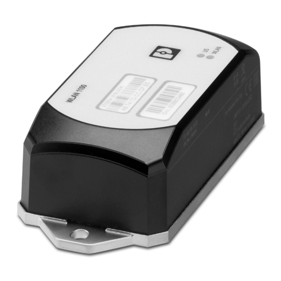
Operation as a WLAN access point, client, or repeater – Supports WLAN 802.11 standards a, b, g, and n – Operation in the 2.4 GHz and 5 GHz band Figure 2-1 FL WLAN 110x/210x 9 / 40 109064_en_00 PHOENIX CONTACT... -
Page 10: Product Versions
Approvals for other countries are available on request. Phoenix Contact hereby declares that this wireless system complies with the basic require- ments and other relevant regulations specified in Directive 2014/53/EU. The EU Declaration of Conformity is to be found in the “Download” area via the following link phoenixcon- tact.net/products. -
Page 11: Fl Wlan 1101/2101
L'exploitation est autorisée aux deux conditions suivantes: l'appareil ne doit pas produire de brouillage, et l'appareil doit accepter tout brouillage radioélectrique subi, même si le brouillage est susceptible d'en compromettre le fonctionnement. 11 / 40 109064_en_00 PHOENIX CONTACT... - Page 12 FL WLAN 1000/2000 NOTICE: Changes or modifications made to this equipment not expressly approved by Phoenix Contact GmbH & Co. KG may void the FCC authorization to operate this equip- ment. Information on radio frequency radiation exposure: This equipment complies with FCC and IC radiation exposure limits set forth for an uncon- trolled environment.
-
Page 13: Firmware
Technical description Firmware For additional information on the firmware of the devices, refer to the separate user man- ual under phoenixcontact.net/products. 13 / 40 109064_en_00 PHOENIX CONTACT... - Page 14 FL WLAN 1000/2000 14 / 40 PHOENIX CONTACT 109064_en_00...
-
Page 15: Mounting / Antenna Configuration
Two integrated WLAN antennas 3.1.1 Housing dimensions The outside dimensions of the FL WLAN 110x and FL WLAN 210x devices are 62.8 mm x 36.5 mm x 113.2 mm (width x height x depth). 15 / 40 109064_en_00 PHOENIX CONTACT... -
Page 16: Electrical Connection
A cable with a cross section of 0.75 mm and a trapezoidal or square crimped ferrule that is 10 mm long is recommended. Always use the appropriate conductor cross section and ferrules to ensure that the cable is fixed securely. 16 / 40 PHOENIX CONTACT 109064_en_00... - Page 17 Ethernet cable. FL WLAN 110x and FL WLAN 210x: Ground the base plate of the device by connecting the mounting screws to a grounded metal surface (functional earth ground/FE). 17 / 40 109064_en_00 PHOENIX CONTACT...
-
Page 18: Mounting The Device On A Level Surface
You can install the device in any mounting position. Figure 3-4 Mounting on a level surface 3.1.3.1 Drill hole template Figure 3-5 Drill hole template 18 / 40 PHOENIX CONTACT 109064_en_00... -
Page 19: Mounting The Device With Cable Feed-Through And Seal
If the device is not mounted directly on a control cabinet, use the FL M32 ADAPTER (Order No. 2702544) to create the seal. In this case, use for example the items 1421126, 1413163 or comparable RJ45 connectors as connectors for the Ethernet cable. 19 / 40 109064_en_00 PHOENIX CONTACT... -
Page 20: Handling The Fl M32 Adapter
The devices of the FL WLAN 110x/210x series contain internal antenna for WLAN com- munication. You should therefore mount the device on the outside of metal objects to en- sure that the WLAN signal can be transmitted. 20 / 40 PHOENIX CONTACT 109064_en_00... - Page 21 Due to its internal antennas, the device should not be located too close to conductive ob- jects, if possible. Maintain a distance of more than 100 mm, if possible. Smaller distances may adversely affect transmission. 21 / 40 109064_en_00 PHOENIX CONTACT...
- Page 22 FL WLAN 1000/2000 22 / 40 PHOENIX CONTACT 109064_en_00...
-
Page 23: Startup And Configuration
CLI or web-based management. Table 4-1 Meaning of the diagnostic and status indicators Des. Color Function Access point Client Green Supply voltage is present (on) WLAN WLAN interface deactivated 23 / 40 109064_en_00 PHOENIX CONTACT... -
Page 24: General Sequence For Startup
All settings of the parameters on the device can be configured via the web interface or Com- mend Line Interface (CLI). For further information, refer to the separate manual “Configura- tion of the FL WLAN 1000/2000 Product family” at phoenixcontact.net/products. 24 / 40 PHOENIX CONTACT 109064_en_00... -
Page 25: Assigning The Ip Address Via Bootp (With Ipassign)
The program is mainly in English for international purposes. However, the program buttons change according to the country-specific settings. The start screen displays the IP address of the PC. This helps when addressing the device in the subsequent steps. • Click on the “Next” button. 25 / 40 109064_en_00 PHOENIX CONTACT... - Page 26 IP parameters of the selected device (IP address, subnet mask, and gateway address) – Any faulty settings Figure 4-2 “Set IP Address” window with faulty settings • Adjust the IP parameters according to your requirements. 26 / 40 PHOENIX CONTACT 109064_en_00...
-
Page 27: Reset To The Factory Settings
Click on the “Finish” button. 4.1.5 Reset to the factory settings The device has a digital input. This digital input on the device is used exclusively to reset the device to the factory settings. 27 / 40 109064_en_00 PHOENIX CONTACT... - Page 28 The operating voltage has to be applied at the digital input for at least 5 seconds. The device is then reset to factory settings and is restarted. 28 / 40 PHOENIX CONTACT 109064_en_00...
-
Page 29: Technical Data
Connection to protective ground By means of lower housing part or additional screw connec- tion Configuration Web-based management via http or https, SNMPv2/v3, CLI via Telnet/SSH, password-protected Pollution degree Overvoltage category None Weight 340 g 29 / 40 109064_en_00 PHOENIX CONTACT... - Page 30 802.11i, WPA PSK, WPA2, AES, TKIP, MAC filter Interfaces RJ45 Ethernet interface Number Connection format RJ45 socket at device, auto negotiation and auto crossing Data transfer rate 10/100 Mbps Segment length 100 m Assignment of the IP address BootP Wireless interface 30 / 40 PHOENIX CONTACT 109064_en_00...
- Page 31 2 to 10 4 to 8 802.11a 36 to 165 802.11na 36 to 64 100 to 165 38 to 62 102 to 159 Security Security mechanisms 802.11i, WPA PSK, WPA2, AES, TKIP, MAC filter 31 / 40 109064_en_00 PHOENIX CONTACT...
-
Page 32: Ordering Data
Access point, FCC approval, only for use in the USA and Canada FL WLAN 1101 2702538 Access point, ETSI approval FL WLAN 2100 2702535 Access point, FCC approval, only for use in the USA and Canada FL WLAN 2101 2702540 32 / 40 PHOENIX CONTACT 109064_en_00... - Page 33 Patch cable, CAT5, pre-assembled, 7.5 m long, 10 pieces FL CAT5 PATCH 7,5 28 32 61 6 Patch cable, CAT5, pre-assembled, 10.0 m long, 10 pieces FL CAT5 PATCH 10 28 32 62 9 33 / 40 109064_en_00 PHOENIX CONTACT...
- Page 34 FL WLAN 1000/2000 34 / 40 PHOENIX CONTACT 109064_en_00...
-
Page 35: Appendixes
“Set IP Address” window with faulty settings ........26 Figure 4-3: “Assign IP Address” window ...............27 Figure 4-4: Connection of the supply voltage and reset on the bottom of the device . Section 5 Appendix A 35 / 40 109064_en_00 PHOENIX CONTACT... - Page 36 FL WLAN 1000/2000 36 / 40 PHOENIX CONTACT 109064_en_00...
-
Page 37: List Of Tables
Section 3 Table 3-1: Connection data for the male connector ..........17 Table 3-2: Pin assignment of RJ45 connectors.............17 Section 4 Table 4-1: Meaning of the diagnostic and status indicators ........23 Section 5 Appendix A 37 / 40 109064_en_00 PHOENIX CONTACT... - Page 38 FL WLAN 1000/2000 38 / 40 PHOENIX CONTACT 109064_en_00...
- Page 39 The receipt of technical documentation (in particular user documentation) does not constitute any further duty on the part of Phoenix Contact to furnish information on modifications to products and/or technical documentation. You are responsible to verify the suitability and intended use of the products in your specific application, in particular with regard to observing the applicable standards and regulations.
- Page 40 Should you have any suggestions or recommendations for improvement of the contents and layout of our manuals, please send your comments to: tecdoc@phoenixcontact.com 40 / 40 PHOENIX CONTACT GmbH & Co. KG • Flachsmarktstraße 8 • 32825 Blomberg • Germany phoenixcontact.com...
- Page 42 PHOENIX CONTACT GmbH & Co. KG Flachsmarktstraße 8 32825 Blomberg, Germany Phone: +49 5235 3-00 Fax: +49 5235 3-41200 E-mail: info@phoenixcontact.com phoenixcontact.com...
Need help?
Do you have a question about the FL WLAN 1000 Series and is the answer not in the manual?
Questions and answers