Table of Contents
Advertisement
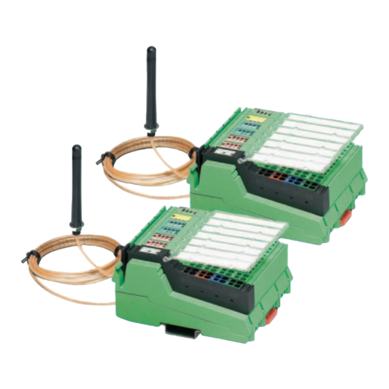
ILB BT ADIO MUX...
Wireless-MUX module with 16 digital inputs,
16 digital outputs, 2 analog inputs, and 2 analog
outputs
Data sheet
7173_en_11
1
Description
The set consists of two modules that form a fixed pair as the
master and slave.
The Wireless-MUX module transmits 16 digital and
2 analog signals bidirectionally by means of wireless
communication. It therefore replaces a 40-wire signal cable.
The wireless solution has been developed specifically for
use under industrial conditions. It is reliable, robust, and
easy to handle.
Please note the maximum permissible transmission power for the country of use.
For the latest country registrations, please visit phoenixcontact.net/products.
Make sure you always use the latest documentation.
It can be downloaded from the product at phoenixcontact.net/products.
© PHOENIX CONTACT
2017-01-25
Features
–
Easy startup, plug and play
–
Bar graph for wireless diagnostics
–
Range of up to 400 m outdoors
–
16 digital inputs
–
16 digital outputs
–
Diagnostic and status indicators
–
2 analog single-ended signal inputs for the connection
of either voltage or current signals
–
2 analog single-ended signal outputs for the connection
of either voltage or current signals
Advertisement
Table of Contents

Related Manuals for Phoenix Contact ILB BT ADIO MUX-OMNI


Summary of Contents for Phoenix Contact ILB BT ADIO MUX-OMNI
-
Page 1: Description
Wireless-MUX module with 16 digital inputs, 16 digital outputs, 2 analog inputs, and 2 analog outputs Data sheet 7173_en_11 © PHOENIX CONTACT 2017-01-25 Description The set consists of two modules that form a fixed pair as the Features master and slave. -
Page 2: Table Of Contents
Connection example......................13 Assignment of terminal points to the remote station .............. 14 Antennas ..........................15 ....................15 11.1 Omnidirectional antennas ..........................18 11.2 Range ..............18 11.3 Typical combinations of antennas and adapter cables 7173_en_11 PHOENIX CONTACT 2 / 18... -
Page 3: Ordering Data
Description Type Order No. Pcs./Pkt. Wireless-MUX set, two modules with 16 digital inputs and ILB BT ADIO MUX-OMNI 2884208 outputs and 2 analog inputs and outputs (0 ... 20 mA, 0 ... 10 V) each, incl. omnidirectional antennas with 1.5 m cable Wireless-MUX set, two modules with 16 digital inputs and... - Page 4 50 Ω impedance Antenna cable, 10 m in length, N (male) -> N (male), RAD-CAB-EF393-10M 2867665 50 Ω impedance Antenna extension cable, 15 m in length, RAD-CAB-EF393-15M 2885634 N (male) -> N (male), 50 Ω impedance 7173_en_11 PHOENIX CONTACT 4 / 18...
-
Page 5: Technical Data
34.25% operating cycle (5 days a week, 12 hours a day) MTTF (mean time to failure) Telcordia standard, 219 Years temperature 40 °C, operating cycle 100 % (7 days a week, 24 hours a day) 7173_en_11 PHOENIX CONTACT 5 / 18... - Page 6 Nominal load, ohmic 12 W (48 Ω) Nominal load, lamp 12 W Nominal load, inductive 12 VA (1.2 H, 50 Ω) Operating frequency with inductive nominal load 0.5 Hz Behavior with overload Auto restart 7173_en_11 PHOENIX CONTACT 6 / 18...
- Page 7 95 % Air pressure (operation) 795 hPa ... 1080 hPa (up to 2000 m above mean sea level) Air pressure (storage/transport) 66 kPa ... 108 kPa (up to 3500 m above mean sea level) 7173_en_11 PHOENIX CONTACT 7 / 18...
- Page 8 An analog channel consists of an input and output. The tolerance values refer to the measuring range final value. They include all tolerances of the input and output. Precision 0.3%, typical; 0.6%, maximum Temperature response 220 ppm/°C 7173_en_11 PHOENIX CONTACT 8 / 18...
-
Page 9: Safety Regulations And Installation Notes
EN 60950. • Operation of the wireless system is only permitted when using accessories available from Phoenix Contact. The use of any other components can lead to the withdrawal of the operating license. 7173_en_11... -
Page 10: Fcc Approval
Japanese Radio Law and Japanese Telecommunications Business Law Compliance The device is granted pursuant to the Japanese Radio Law ( This device should not be modified (otherwise the granted designation number will become invalid). Contains: XXX-XXXXXX 7173_en_11 PHOENIX CONTACT 10 / 18... -
Page 11: Local Diagnostic And Status Indicators
If the error LED of a group of 16 outputs lights up (e.g., connector 2 and 3), this indicates that a short circuit or overload is present at one or more of the outputs in this group. 7173_en_11 PHOENIX CONTACT 11 / 18... -
Page 12: Terminal Point Assignment
Shield connection Analog input connector Connector 7: Analog IN Voltage input, channel 1 Voltage input, channel 2 Current input, channel 1 Current input, channel 2 AGND Analog ground AGND Analog ground Shield connection Shield connection 7173_en_11 PHOENIX CONTACT 12 / 18... -
Page 13: Basic Circuit Diagram
The numbers above the device identify the connector slots. OUT 4 IN 6 Figure 5 Connection example Actuator at the voltage output (channel 1) Actuator at the current output (channel 2) Active sensor with current output (channel 1) Active sensor with voltage output (channel 2) 7173_en_11 PHOENIX CONTACT 13 / 18... -
Page 14: Assignment Of Terminal Points To The Remote Station
Connector 7: Analog IN Terminal point 1.1 Slave Slot Connector 6: Analog OUT Terminal point 1.1 Slave Slot Connector 7: Analog IN Terminal point 1.1 Master Slot Connector 6: Analog OUT Terminal point 1.1 7173_en_11 PHOENIX CONTACT 14 / 18... -
Page 15: Antennas
Link Quality display during startup. • Install the antennas in such a way that at least three LEDs light up. Depending on the system, occasional fluctuations in the display may occur during operation. 7173_en_11 PHOENIX CONTACT 15 / 18... - Page 16 Cable length 1.5 m Connection RSMA (male) Horizontal / vertical apex angle 360°/75° VSWR ≤2 Wall mounting -150 Figure 11 Mounting brackets -120 Figure 9 Horizontal -150 -120 Figure 12 Wall mounting Figure 10 Vertical 7173_en_11 PHOENIX CONTACT 16 / 18...
- Page 17 ILB BT ADIO MUX... Mounting on the control cabinet Ø10 Figure 14 Mounting on the control cabinet Figure 13 Control cabinet feed-through 7173_en_11 PHOENIX CONTACT 17 / 18...
-
Page 18: Range
Omnidirectional antenna, 2 dBi, supplied as In order to minimize signal losses, keep the antenna cable standard as short as possible. Figure 16 Directional antenna, 9 dBi, with surge protection PHOENIX CONTACT GmbH & Co. KG • 32823 Blomberg • Germany 7173_en_11 18 / 18 phoenixcontact.com...
Need help?
Do you have a question about the ILB BT ADIO MUX-OMNI and is the answer not in the manual?
Questions and answers