Table of Contents
Advertisement
PP-RJ-...
Patch panels
Data sheet
107962_en_01
1
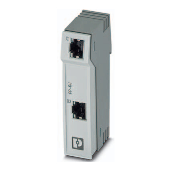
Description
The component is an Ethernet patch panel for DIN rail
mounting. It represents the transition of the field cabling to
the internal control cabinet cabling.
The connection from the patch panel to the end device is
ensured with a prefabricated patch cable via the RJ45
socket (CAT5e).
Make sure you always use the latest documentation.
It can be downloaded from the product at phoenixcontact.net/products.
The PP-RJ... patch panels are compatible with the devices of the FL-PP... product family.
When replacing FL-PP... devices with PP-RJ... devices, strip an additional 1.4 cm of the cable sheath away.
© PHOENIX CONTACT
2018-12-18
Features
–
10/100/1000 Mbps
–
Mounting on a DIN rail
–
Safe shield connection to ground potential
–
Various connection options depending on the product
version
–
RJ45 socket
–
Screw terminal blocks
–
Push-in connection
–
IDC connection
Advertisement
Table of Contents

Related Manuals for Phoenix Contact PP-RJ Series


Summary of Contents for Phoenix Contact PP-RJ Series
-
Page 1: Description
PP-RJ-... Patch panels Data sheet 107962_en_01 © PHOENIX CONTACT 2018-12-18 Description The component is an Ethernet patch panel for DIN rail Features mounting. It represents the transition of the field cabling to – 10/100/1000 Mbps the internal control cabinet cabling. –... -
Page 2: Table Of Contents
......................13 Terminal assignment .......................... 13 Stripping ................... 13 Screw terminal blocks (only PP-RJ-SC) ................13 Push-in terminal blocks (only PP-RJ-SCC) ..................14 IDC terminal blocks (only PP-RJ-IDC) ..................14 Shield contacting with strain relief 107962_en_01 PHOENIX CONTACT 2 / 15... -
Page 3: Ordering Data
2 x 2 x 0.22 mm², solid conductor, shielded, outer sheath: 7.8 mm diameter, inner sheath: 5.75 mm ±0.15 mm diameter, preassembled on both sides with RJ45 plug, crossover or line, network cable, number of positions: 4, 100 Mbps, CAT5 107962_en_01 PHOENIX CONTACT 3 / 15... - Page 4 2891482 Patch cable, CAT6, pre-assembled, 2.0 m FL CAT6 PATCH 2,0 2891589 Patch cable, CAT6, pre-assembled, 3.0 m FL CAT6 PATCH 3,0 2891686 Patch cable, CAT6, pre-assembled, 5.0 m FL CAT6 PATCH 5,0 2891783 107962_en_01 PHOENIX CONTACT 4 / 15...
- Page 5 Diagonal cutter Network cable, Ethernet CAT6 (10 Gbps), 8-position, VS-OE-OE-94F/... 1417359 PUR halogen-free, water blue RAL 5021, shielded, free cable end, on free cable end, cable length: Free entry (0.5 ... 400 m) 107962_en_01 PHOENIX CONTACT 5 / 15...
-
Page 6: Technical Data
< 57 V DC (with UL approval) Maximum output current 725 mA (per channel) Serial transmission speed 10/100/1000 Mbps Transmission length 100 m (including patch cables) Connection line twisted pair, shielded, CAT5 or better Pin assignment 107962_en_01 PHOENIX CONTACT 6 / 15... - Page 7 II 3 G Ex nA IIC Gc U Please follow the special installation instructions in the documentation! UL, USA UL 60079-0 Ed. 6 / UL 60079-15 Ed. 4 UL, Canada CSA 22.2 No. 60079-0 Ed. 3 / CSA 22.2 No. 60079-15:16 Noxious gas test ISA-S71.04-1985 G3 Harsh Group A 107962_en_01 PHOENIX CONTACT 7 / 15...
-
Page 8: Safety Regulations And Installation Notes
The product is not designed for use in potentially dust- explosive atmospheres. • The product must be stopped and immediately removed from the Ex area if it is damaged, has been subjected to an impermissible load, stored incorrectly, or if it malfunctions. 107962_en_01 PHOENIX CONTACT 8 / 15... -
Page 9: Ul Notes
The device has to be built in the final safety enclosure, which has adequate rigidity according to UL 61010-1, UL 61010-2-201 and meets the requirements with respect to spread of fire. Use copper conductors only. 107962_en_01 PHOENIX CONTACT 9 / 15... -
Page 10: Product Description
PP-RJ-... Product description 62,7 23,6 55,2 Figure 1 Dimensions PP-RJ-RJ 62,7 23,6 55,2 Figure 2 Dimensions 107962_en_01 PHOENIX CONTACT 10 / 15... -
Page 11: Function Elements
Function elements Figure 3 PP-RJ-RJ Figure 5 PP-RJ-SCC Figure 4 PP-RJ-SC Figure 6 PP-RJ-IDC Shielded RJ45 socket (TP port) Port 2 depending on product version, see above Shield contact spring (shield contacting with strain relief) 107962_en_01 PHOENIX CONTACT 11 / 15... -
Page 12: Installation
Push down the locking tab with a screwdriver, needle- nose pliers or similar. • Slightly pull the bottom edge of the device away from the mounting surface. • Pull the device away from the DIN rail. 107962_en_01 PHOENIX CONTACT 12 / 15... -
Page 13: Terminal Assignment
(5.5 cm). • Strip the cable. • Keep the aluminum foil on the single wires as far as possible. • Fold back 20 mm of the braided shield backwards over the outer sheath. 107962_en_01 PHOENIX CONTACT 13 / 15... -
Page 14: Idc Terminal Blocks (Only Pp-Rj-Idc)
Open the shield contact spring. • If the spring is latched in place, use a screwdriver to open it. Figure 16 Inserting the cable • Place the cable with the folded braided shield into the guiding shaft. 107962_en_01 PHOENIX CONTACT 14 / 15... - Page 15 • Organize the wires so that you can close the cover. Fully snap in the foldable cover to prevent unintentional opening. PHOENIX CONTACT GmbH & Co. KG • 32823 Blomberg • Germany 107962_en_01 15 / 15 phoenixcontact.com...
Need help?
Do you have a question about the PP-RJ Series and is the answer not in the manual?
Questions and answers