Phoenix Contact Axioline F User Manual
Module with integrated safety logic and safe digital outputs
Hide thumbs
Also See for Axioline F:
- User manual (148 pages) ,
- User manual (78 pages) ,
- User manual (44 pages)

Related Manuals for Phoenix Contact Axioline F


Summary of Contents for Phoenix Contact Axioline F
- Page 1 Axioline F module with integrated safety logic and safe digital outputs User manual...
- Page 2 User manual Axioline F module with integrated safety logic and safe digital outputs 2016-01-26 Designation: UM EN AXL F LPSDO8/3 1F Revision: This user manual is valid for: Designation HW/FW revision Order No. AXL F LPSDO8/3 1F 00/100 2702171 PHOENIX CONTACT...
- Page 3 How to contact us Internet Up-to-date information on Phoenix Contact products and our Terms and Conditions can be found on the Internet at: phoenixcontact.com Make sure you always use the latest documentation.
- Page 4 The receipt of technical documentation (in particular user documentation) does not constitute any further duty on the part of Phoenix Contact to furnish information on modifications to products and/or technical documentation. You are responsible to verify the suitability and intended use of the products in your specific application, in particular with regard to observing the applicable standards and regulations.
-
Page 5: Table Of Contents
Parameterization errors ................ 20 Process data words ..................... 21 2.10 Programming data/configuration data..............21 Integration of the Axioline F local bus ..................23 Supply voltage of the module logic ..............23 Supply voltage U ....................24 DC distribution network according to IEC 61326-3-1 ........... 25 Terminal point assignment................... - Page 6 AXL F LPSDO8/3 1F Electrical installation .................... 31 4.2.1 Electrical installation of the Axioline F station ........31 4.2.2 Electrical installation of the module ............31 Parameterization of the module ....................33 Parameterization in a SafetyBridge system ............33 Parameterization of the safe outputs ..............34 Behavior of the outputs in the event of enabled switch-off delay for stop category 1 ....................
- Page 7 Application errors ................. 92 A 13 Startup and restart ....................93 A 13.1 Startup/restart following power up ............93 A 13.2 Restart after triggering a safety function ..........93 A 14 Memory sizes for the safety logic................ 94 106889_en_00 PHOENIX CONTACT...
- Page 8 Checklists for the AXL F LPSDO8/3 1F module..........102 B 2.1 Planning ..................102 B 2.2 Assembly and electrical installation ..........103 B 2.3 Startup and parameterization ............104 B 2.4 Validation ..................105 Appendix: index ........................107 Appendix: revision history.......................109 PHOENIX CONTACT 106889_en_00...
-
Page 9: For Your Safety
– SafetyBridge system – Components used – Axioline F product range – Operation of the software tools – Safety regulations in the field of application In the context of the use of the system, the following operations must only be carried out by qualified personnel: –... -
Page 10: Electrical Safety
In this case, the correct operation of the safety module can no longer be ensured. In the event of an error, send the module to Phoenix Contact or contact Phoenix Contact immediately and engage a service engineer. -
Page 11: Safety Of The Machine Or System
Safe shutdown of contactors, motors (24 V DC), valves, ohmic, inductive, and capacitive loads The module is not suitable for applications in which stop category 1 also has to be observed in the event of an error. 106889_en_00 PHOENIX CONTACT... -
Page 12: Documentation
For the SafetyBridge system function blocks Please also observe the information on the bus system used. Documentation for the Axioline F: system and installation user manual, UM EN AXL F SYS INST Axioline F product range Documentation for the bus coupler used... -
Page 13: Product Description
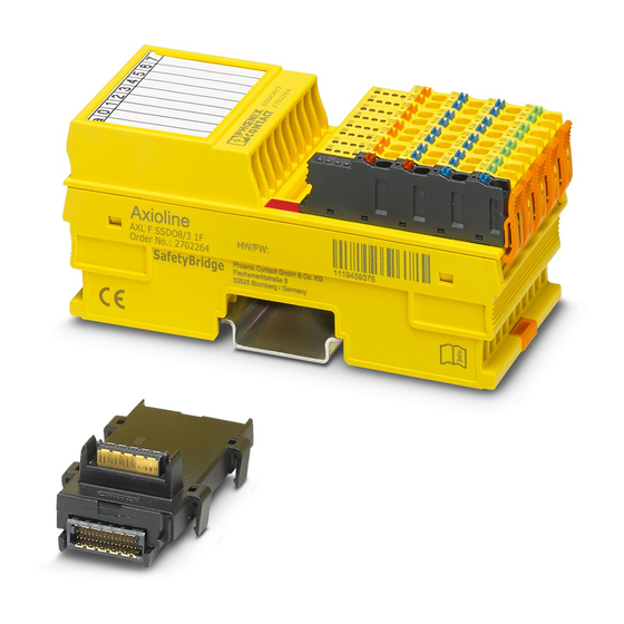
Short description of the module The AXL F LPSDO8/3 1F module is an output module with integrated safety logic for use at any point in an Axioline F station. The module is designed for use in the SafetyBridge system. The SafetyBridge address is set via a DIP switch. -
Page 14: Structure Of The Module
Connector for connecting the supply voltage Function identification I/O connector Diagnostics and status indicators DIP switch More detailed information on setting the switch: see Section 4.1.3 “Setting the DIP switch” on page 28. Housing dimensions 53,6 Figure 2-2 Housing dimensions (in mm) PHOENIX CONTACT 106889_en_00... -
Page 15: Safe Digital Outputs
These test pulses are visible at the output and can trigger undesirable reactions with quick responding actuators. The test pulses are either light pulses (brief activation) which can be disabled or dark pulses (brief deactivation) which cannot be disabled. 106889_en_00 PHOENIX CONTACT... -
Page 16: Connection Options For Actuators Depending On The Parameterization
SIL 3/SILCL 3/Cat. 4/PL e For connection example, see page * If the test pulses are disabled, a cross-circuit between the outputs is only detected if the output is enabled. To achieve Cat. 3, two-channel actuators are usually used. PHOENIX CONTACT 106889_en_00... -
Page 17: Local Diagnostics And Status Indicators
(Only applies if UI is on or flashing at the same time.) Red on Hardware fault. Communication to the higher-level controller is disabled. The module has entered the safe state (failure state). Flashing red The module is not parameterized. 106889_en_00 PHOENIX CONTACT... - Page 18 Status of each output from 0 - 7 Output at logic “0”. Green on Output at logic “1”. 10 - 17 Diagnostics for each output from 0 - 7 No error present at the output. Red on Error at the output (e.g., short circuit). PHOENIX CONTACT 106889_en_00...
-
Page 19: Safe State
51. Information on which errors are detected and when: see Section 6 “Connection examples for safe outputs” on page 37. If an error occurs on a channel of an output parameterized as “two-channel”, the other corresponding channel also enters the safe state. 106889_en_00 PHOENIX CONTACT... -
Page 20: Device Errors
The module switches to the safe state following parameterization errors. The FS LED on the module flashes. In the event of faulty parameterization, a diagnostic message is transmitted to the controller: see Section 8 “Errors: messages and removal” on page 51. PHOENIX CONTACT 106889_en_00... -
Page 21: Process Data Words
Product description Process data words The module occupies 24 words in the Axioline F system. Access the process data words via the “Operate” function block. The module has feedback data and enable data. See Section A 5, “Feedback data” and “Enable principle”... - Page 22 AXL F LPSDO8/3 1F PHOENIX CONTACT 106889_en_00...
-
Page 23: Integration Of The Axioline F Local Bus
Integration of the Axioline F local bus The module is integrated for operation in an Axioline F station. More detailed information on the structure of an Axioline F station: see UM EN AXL F SYS INST user manual. Supply voltage of the module logic The supply voltage for the module logic is generated in the bus coupler and led to the Axioline F module via the bus base module. -
Page 24: Supply Voltage U
24 V DC external fuse (PELV) 230 V or supply at the Axioline F module 24 V GND for supply at a bus coupler or a power terminal 105739B000_en Figure 3-1... -
Page 25: Dc Distribution Network According To Iec 61326-3-1
Terminal point assignment Figure 3-2 Terminal point assignment The Axioline F connectors are supplied with the module. They are color coded and marked for connection. Only use the connectors supplied with the module. The following applies for the tables below: –... - Page 26 Parasitic voltages can result in the loss of the safety function. • Connect the actuator ground to the ground terminal point of the corresponding output on the Axioline F connector. An external ground may not be used. PHOENIX CONTACT 106889_en_00...
-
Page 27: Assembly, Removal, And Electrical Installation
• Before assembling or removing the module, disconnect the power to the module and the entire Axioline F station and make sure that the system cannot be switched on again. •... -
Page 28: Setting The Dip Switch
The set address is only applied on power up. If the address is adjusted during operation, the module responds with a failure state. For additional information on addressing, please refer to “SafetyBridge address assignment” on page 76. PHOENIX CONTACT 106889_en_00... -
Page 29: Mounting And Removing The Module
Insert a suitable tool (e.g., bladed screwdriver) into the upper and lower snap- on mechanisms (base latches) of the module one after the other to release it (A). • Remove the module perpendicular to the DIN rail (B). 106889_en_00 PHOENIX CONTACT... - Page 30 • Press firmly on the connector. Make sure that the locking latch snaps in. Remove • Release the locking latch (A). • Tilt the connector upwards slightly (B). • Remove the connector from the module (C). PHOENIX CONTACT 106889_en_00...
-
Page 31: Electrical Installation
– Connecting the supply voltages for the Axioline F station • Carry out electrical installation for the Axioline F station according to the following user manuals: – Axioline F: system and installation user manual, UM EN AXL F SYS INST –... - Page 32 AXL F LPSDO8/3 1F PHOENIX CONTACT 106889_en_00...
-
Page 33: Parameterization Of The Module
FS LED flashes to indicate that the parameterization is invalid. In addition, the error is indicated at the controller. • In this case, check and correct the settings. Information on error messages and troubleshooting: see Section 8 “Errors: messages and removal” on page 51. 106889_en_00 PHOENIX CONTACT... -
Page 34: Parameterization Of The Safe Outputs
The default values are shown in bold. Test pulses If the light pulses are disabled, cross-circuits and short circuits cannot be detected when the output is switched off. However, outputs parameterized as “Not used” are tested with test pulses. PHOENIX CONTACT 106889_en_00... -
Page 35: Behavior Of The Outputs In The Event Of Enabled Switch-Off Delay For Stop Category 1
WARNING: Incorrect/insufficient safety distances Selecting the wrong switch-off delay can result in incorrect safety distances being designed. • When designing the safety distances, take the selected switch-off delay into consideration. 106889_en_00 PHOENIX CONTACT... - Page 36 AXL F LPSDO8/3 1F PHOENIX CONTACT 106889_en_00...
-
Page 37: Connection Examples For Safe Outputs
The examples only describe the options for the electrical connection of controlled devices/actuators to the safe outputs. Should you have any questions regarding your applications, please contact the Phoenix Contact safety hotline: see Section 1.8 “Safety hotline” on page 12. The following are specified for each example: 106889_en_00... - Page 38 Only errors between outputs, which are on the same connector, are described. For example, in the event of correct installation, cross-circuits with outputs of other connectors cannot occur. PHOENIX CONTACT 106889_en_00...
-
Page 39: Notes On The Protective Circuit Of External Relays/Contactors (Freewheeling Circuit)
PFD and PFH depending on the SIL/SILCL Safety integrity SIL 2/SILCL 2 1% of 10 1% of 10 SIL 3/SILCL 3 1% of 10 1% of 10 Performance level Use standard EN ISO 13849-1 to determine the performance level. 106889_en_00 PHOENIX CONTACT... - Page 40 An accumulation of errors must not result in the loss of the safety function. Following the third error, evaluation can be aborted if the probability of further errors occurring is low. PHOENIX CONTACT 106889_en_00...
-
Page 41: Single-Channel Assignment Of Safe Outputs
Parasitic voltages can result in the loss of the safety function. • Connect the actuator ground to the ground terminal point of the corresponding output on the Axioline F connector. An external ground may not be used. Basic specifications Actuator... - Page 42 Typical parameterization Parameterization Parameterized as Comment Assignment Used Test pulses (output disabled) Enabled Or disabled (in software: test impulses (output switched off)) Switch-off delay for stop Enabled Or disabled category 1 Output Single-channel Enable Enabled Or disabled PHOENIX CONTACT 106889_en_00...
-
Page 43: Two-Channel Assignment Of Safe Outputs
• Connect the actuator ground to the ground terminal point of the corresponding output on the Axioline F connector. An external ground may not be used. The failure detection time does not have to be taken into consideration for two-channel assignment. - Page 44 Acknowledging an error activates the outputs again. This can result in unexpected machine startup. • Before acknowledging an error, make sure that no persons can access the danger zone. SF = safety function OUTx = diagnostic message (LED) for each output X PHOENIX CONTACT 106889_en_00...
- Page 45 Channel 1 Channel 2 Assignment Used Used Test pulses (output disabled) Enabled Enabled (in software: test impulses (output switched off)) Switch-off delay for stop Enabled Enabled Or disabled category 1 Output Two-channel Two-channel Enable Enabled Enabled Or disabled 106889_en_00 PHOENIX CONTACT...
- Page 46 AXL F LPSDO8/3 1F PHOENIX CONTACT 106889_en_00...
-
Page 47: Startup And Validation
– Make sure that functional earth ground is connected. Connect the necessary voltages to the Axioline F station. UM EN AXL SYS INST user manual or documentation for the module Connect the necessary voltages (U ) to the module. -
Page 48: Startup Mode
The red CM LED indicates that the device is in startup mode. In the Startup+ software, enter the address set on the device. For additional information on the Startup+ software, refer to the documentation for the software. The software can be downloaded free of charge at phoenixcontact.net/products. PHOENIX CONTACT 106889_en_00... -
Page 49: Restart After Replacing A Module
• Before assembling or removing the module, disconnect the power to the module and the entire Axioline F station and make sure that the system cannot be switched on again. •... - Page 50 AXL F LPSDO8/3 1F PHOENIX CONTACT 106889_en_00...
-
Page 51: Errors: Messages And Removal
Module replacement following an error If the safety module is replaced in the event of an error, proceed as described in “Assembly, removal, and electrical installation” on page 27 and “Restart after replacing a module” on page 49. 106889_en_00 PHOENIX CONTACT... -
Page 52: Note About The Error Codes
4021: no error; the SafetyBridge address is displayed The error codes are listed in ascending order in Table 8-2 “Error codes”. If error codes are indicated by the system which do not appear in the table, please contact Phoenix Contact. PHOENIX CONTACT 106889_en_00... -
Page 53: Error Codes
0058 OUT0_Ch2 restart following an error- 0059 OUT1_Ch2 – Short circuit in the free selftest. The states 005A OUT2_Ch2 external wiring at the outputs are 005B OUT3_Ch2 transmitted immediately. If the error occurs permanently: Replace module 106889_en_00 PHOENIX CONTACT... - Page 54 If acknowledgment is not OUT: possible: red on Replace module Acknowledgment: Acknowledgment triggers the message and results in a restart following an error- free selftest. The states at the outputs are transmitted immediately. PHOENIX CONTACT 106889_en_00...
- Page 55 02C0 OUT0_Ch1&2 parameterization – A reserved value has 02C1 OUT1_Ch1&2 been selected for the Resend parameter data 02C2 OUT2_Ch1&2 “Assignment of the to the module 02C3 OUT3_Ch1&2 outputs” (deactivate/activate parameterization “Operate” block) Acknowledgment: not possible 106889_en_00 PHOENIX CONTACT...
- Page 56 Compare HW flashing record configuration with SAFECONF project – Parameter data record does not match the Check assignment of device process data at the “Operate” block Resend parameter data to the module (deactivate/activate “Operate” block) Acknowledgment: not possible PHOENIX CONTACT 106889_en_00...
- Page 57 0441 SD on Internal error Module is in the safe state Please contact Phoenix Contact. 0446 Acknowledgment: not possible 0447 SD on Incorrect configuration Module is in the safe state 1.
- Page 58 Not possible. Restart is only possible following power up and error-free selftest. 1YYY FS on Internal error Module is in the safe state Please contact Phoenix Contact. Acknowledgment: not possible 4YYY No error Module is in the safe state 1. Check DIP switch...
-
Page 59: Maintenance, Repair, Decommissioning, And Disposal
In this case, the correct operation of the safety module can no longer be ensured. • In the event of an error, send the module to Phoenix Contact or contact Phoenix Contact immediately and engage a service engineer. Decommissioning and disposal Carry out decommissioning according to the requirements of the machine or system manufacturer. - Page 60 AXL F LPSDO8/3 1F PHOENIX CONTACT 106889_en_00...
-
Page 61: 10 Technical Data And Ordering Data
According to IEC 60439-1, derived from IEC 60664-1 Protection class III (PELV), IEC 61140, EN 61140, VDE 0140-1 Gases that may endanger functions according to DIN 40046-36, DIN 40046- Not resistant to gas that may endanger functions (sulfur dioxide (SO hydrogen sulfide (H 106889_en_00 PHOENIX CONTACT... - Page 62 General data [...] Resistance of the housing material to fungal decay Resistant Ambient compatibility Not resistant to organic chlorine compounds Connection data for Axioline F connectors Connection method Spring-cage terminal blocks Conductor cross section Solid: 0.5 mm to 1.5 mm Flexible without sleeve: 0.25 mm...
- Page 63 Section 2.7 “Local diagnostics and status indicators” on page 17 External protection 8 A slow-blow, maximum Safe digital outputs Quantity 4 two-channel or 8 single-channel (positive switching) Supply From supply voltage U Maximum output current per output (channel) 1.5 A (from 45°C according to CUL 106889_en_00 PHOENIX CONTACT...
- Page 64 Please note that the load on a switch-on pulse (light test) of 1 ms must not fail or respond in a safety-critical way. • Please take this into consideration when selecting the actuator. Maximum duration of the test pulses (when switched on) 3 ms (depending on the load capacity) PHOENIX CONTACT 106889_en_00...
-
Page 65: Conformance With Emc Directive
WARNING: Loss of safety function Parasitic voltages can result in the loss of the safety function. • Connect the actuator ground to the ground terminal point of the corresponding output on the Axioline F connector. An external ground may not be used. •... -
Page 66: Ordering Data: Module
Axioline F: diagnostic registers and error messages SafetyBridge User manual: UM EN AXL F LPSDO8/3 1F 2702171 Axioline F module with integrated safety logic and safe digital outputs SafetyBridge technology integration package for controllers from SBT_V3_PLC_Integration_Packages_1.8.exe 2702171 Phoenix Contact, Rockwell and Siemens (S7-1200 as of CPU 1214C, S7-1500, S7-300), Schneider as well as CODESYS-based controllers. -
Page 67: A Appendix: Safetybridge System
– Equivalent – MutingPar (incl. override) – ESPE – Reset – E-STOP – TestableSafetySensor – GuardLocking – TwoHandControl II – GuardMonitoring – TwoHandControl III – Implicit enable Feedback of local safe output data Forwarding of safe outputs 106889_en_00 PHOENIX CONTACT... - Page 68 – IB IL 24 LPSDO 8 V3-PAC The AXL F LPSDO8/3 1F logic module from the Axioline F series can operate satellites from the Inline series. A logic module from the Inline series cannot operate satellites from the Axioline F series.
-
Page 69: A 2 System Topology
Communication Communication takes place via the standard controller and the standard bus system using safe data packets. System The system consists of a standard controller and up to 31 SafetyBridge islands. 106889_en_00 PHOENIX CONTACT... -
Page 70: A 2.2 Network And Controller Requirements
LEDs, and can be evaluated by the user. The safe I/O devices are from the Axioline F product range. Their design and interfaces correspond to standard Axioline F I/O devices. This means that no additional installation effort is required. -
Page 71: A 2.4 Cross Communication
SAFECONF hardware toolbox Once you have inserted the AXL F LPSDO8/3 1F SL in the hardware editor, the module appears with 16 safe input and output signals. Figure A-3 SAFECONF project for the LPSDO V3 “master” module 106889_en_00 PHOENIX CONTACT... - Page 72 AXL F LPSDO8/3 1F SL module, which can be obtained from the “External signals” toolbox in the corresponding SAFECONF project for the AXL F LPSDO8/3 1F SL module. Figure A-5 SAFECONF project for the LPSDO V3 “slave” module PHOENIX CONTACT 106889_en_00...
- Page 73 Linking islands in series modifies the total safety response time of the system. • When calculating the total safety response time, please note the modified basis for calculation in “Time response in the SafetyBridge system” on page 87. 106889_en_00 PHOENIX CONTACT...
- Page 74 LPSDO 1 LPSDO 2 LPSDO 3 LPSDO 4 SSDI 2.1 SSDI 2.2 SSDO 2.4 SSDI 3.1 SSDI 3.2 SSDO 3.3 SSDO 3.4 SSDI 4.1 SSDI 4.2 SSDO 4.4 SSDO 2.3 SSDO 4.3 Figure A-6 Hierarchical topology (tree structure) PHOENIX CONTACT 106889_en_00...
- Page 75 SSDO 3.3 SSDO 3.4 LPSDO 1 LPSDO 2 LPSDO 3 SSDI 1.1 SSDI 1.2 SSDI 1.3 SSDO 1.4 SSDI 2.1 SSDI 2.2 SSDO 2.3 SSDI 3.1 SSDI 3.2 SSDO 3.3 SSDO 3.4 Figure A-7 Flat topology (line structure) 106889_en_00 PHOENIX CONTACT...
-
Page 76: A 3 Safetybridge Address Assignment
SafetyBridge address for the AXL F LPSDO8/3 1F Operatin Reserved SafetyBridge address g mode Island number Reserved off/on to 31 Table A-5 SafetyBridge address, e.g., AXL F SSDI8/4 1F Operatin Reserved SafetyBridge address g mode Island number Satellite number off/on to 31 to 16 PHOENIX CONTACT 106889_en_00... - Page 77 Satellite number SafetyBridge address AXL F LPSDO8/3 1F AXL F SSDO8/3 1F Position 1 AXL F SSDI8/4 1F Position 2 AXL F SSDO8/3 1F Position 3 AXL F SSDO8/3 1F Position 4 AXL F SSDI8/4 1F Position 5 106889_en_00 PHOENIX CONTACT...
- Page 78 Assigned AXL F SSDO8/3 1F / AXL F SSDI8/4 1F 00001 00101 (25 00010 00101 (45 Assigned AXL F SSDO8/3 1F / AXL F SSDI8/4 1F 00001 00110 (26 Assigned AXL F SSDO8/3 1F 00001 00111 (27 Assigned AXL F SSDI8/4 1F PHOENIX CONTACT 106889_en_00...
- Page 79 “Display address switch”. Figure A-9 Island number 1 (red in Figure A-8) in the SAFECONF hardware editor Figure A-10 Island number 2 (green in Figure A-8) in the SAFECONF hardware editor 106889_en_00 PHOENIX CONTACT...
-
Page 80: A 4 Safetybridge V3 System Handling In Various Control Systems
When the enable function is enabled, the relevant safe local output is ANDed bit-by-bit with the corresponding output bit of the standard controller. This output is then only set if the result of the safety function calculation permits this and the standard controller has set the corresponding output. PHOENIX CONTACT 106889_en_00... - Page 81 AXL F LPSDO8/3 1F; bit x See block description for the relevant controller. & Standard function block for ANDing OUTx_Chy Output x, channel y Internal functionality that is enabled by means of parameterization; not visible in SAFECONF 106889_en_00 PHOENIX CONTACT...
- Page 82 Not relevant 0_Q04 OUT2_Ch1 Two-channel Enabled 0_Q05 OUT2_Ch2 Two-channel Enabled Not relevant 0_Q06 OUT3_Ch1 Single-channel Disabled Not relevant 0_Q07 OUT3_Ch2 Single-channel Disabled Not relevant For two-channel parameterization, only use the process data bit of the first channel. PHOENIX CONTACT 106889_en_00...
-
Page 83: A 7 Diagnostics
The corresponding error message is transmitted to the AXL F LPSDO8/3 1F and the standard controller. For more detailed information on error detection at the safe outputs, please refer to the user manual for the AXL F SSDO8/3 1F module. 106889_en_00 PHOENIX CONTACT... -
Page 84: A 7.2 Detection Of Device Errors
For instructions on acknowledgement, refer to the relevant block help and quick start guides for the AXL F LPSDO8/3 1F. The quick start guides for the AXL F LPSDO8/3 1F are included in the SafetyBridge V3 integration package, which is available to download. See “Download data: documentation” on page 66. PHOENIX CONTACT 106889_en_00... -
Page 85: A 8 Configuration, Parameterization, And Download
To roughly estimate the memory required, please use the information in “Memory sizes for the safety logic” on page 94. 106889_en_00 PHOENIX CONTACT... -
Page 86: A 8.2 Downloading The Configuration And Parameter Data Record
For safe input modules, the safe state is the transmission of the “safe state value” (“0”) in the image of the affected inputs to the affected logic module. Bus system For transmission on the bus, the safe state is the transmission of the value “0”. PHOENIX CONTACT 106889_en_00... -
Page 87: A 10 Time Response In The Safetybridge System
Comment Required shutdown time for the safety function Determined from the application, e.g., from the required times according to the distance of a light grid The typical response time depends on the network and standard controller used. 106889_en_00 PHOENIX CONTACT... -
Page 88: A 10.2 Shutdown Times
Determined from the application, e.g., from the required times according to the distance of a light grid Response time of the sensor Sensor data sheet Processing time of the input User manual for the safe input module PHOENIX CONTACT 106889_en_00... - Page 89 If several inputs are involved in the safety function, the longest processing time of the inputs involved is included in the calculation. If several AXL F SSDI8/4 1F devices are involved in a safety function, the longest F- Watchdog time is included in the calculation. 106889_en_00 PHOENIX CONTACT...
-
Page 90: A 11 Achievable Safety Depending On The Modules Used
AXL F LPSDO8/3 1F A 11 Achievable safety depending on the modules used Phoenix Contact recommends using the SISTEMA software utility to determine the achievable safety. The SISTEMA software utility for the safety of control systems on machines can be... -
Page 91: A 12.1 Critical System Or Device Errors
It is not possible to acknowledge the error or continue operating without modifying the parameter or configuration data of the affected device. 106889_en_00 PHOENIX CONTACT... -
Page 92: A 12.3 Communication Errors
A 12.5 Application errors All errors that can occur within the safety logic configured in SAFECONF and can be detected and acknowledged by the safe function blocks are assigned to this class. They include, for example: PHOENIX CONTACT 106889_en_00... -
Page 93: A 13 Startup And Restart
The SafetyBridge system resets a safety-related output to “1” automatically when the safety function trigger is reset. WARNING: Unexpected machine startup • If you do not want the machine to restart automatically, configure the safety logic accordingly. 106889_en_00 PHOENIX CONTACT... -
Page 94: A 14 Memory Sizes For The Safety Logic
GuardLocking, GuardMonitoring, ModeSelector, Reset, TestableSafetySensor, TwoHandControlTypeII, TwoHandControlTypeIII Safety functions: CTUD, F_TRIG, PULSE_GEN, R_TRIG, RS, SR, TOF, TON, TP Standard functions: CTUD, F_TRIG, PULSE_GEN, R_TRIG, RS, SR, TOF, TON, TP Logic functions: AND, EN_OUT, EQ, NOT_EQ, NOT, OR, PHOENIX CONTACT 106889_en_00... -
Page 95: B Appendix: Checklists
These requirements must be met for a safety application, in order to complete the relevant phase using the checklist. Requirement (optional) These requirements are optional. For points that are not met, please enter an appropriate comment in the relevant field. 106889_en_00 PHOENIX CONTACT... -
Page 96: B 1 Checklists For The Safetybridge System
Has it been ensured that any person intentionally starting hazardous movements can only do so with a direct view of the danger zone? Are there fewer than 6 serial chains between the logic modules within a safety function? PHOENIX CONTACT 106889_en_00... - Page 97 No Comment Are all measures that are based on applicable standards planned? Have the Axioline F specifications (e.g., cabling, supply) been observed? Have the accessories to be used been planned (e.g., cables, connectors)? Are the specifications for parameterization, assembly, electrical installation, startup, and...
-
Page 98: B 1.2 Configuration And Parameterization
Has it been ensured that an acknowledgment can only be executed by an intentional user action? (Not configured as “automatic”.) Has the checklist/project information been processed in SAFECONF (“Project... Project Info” menu item)? Requirement (optional) No Comment Date Signature (editor) Date Signature (test engineer) PHOENIX CONTACT 106889_en_00... -
Page 99: B 1.3 Startup
During startup, is it ensured that any person starting hazardous movements intentionally can only do so with a direct view of the danger zone? Requirement (optional) No Comment Are startup specifications applicable? If applicable, have startup specifications been met? Date Signature (editor) Date Signature (test engineer) 106889_en_00 PHOENIX CONTACT... -
Page 100: Safety Functions
B 1.4 Safety functions Enter all the safety functions for your application in this checklist. Checklist for checking safety functions Equipment identification Date Author Test engineer Comment Safety functions Comment Date Signature (editor) Date Signature (test engineer) PHOENIX CONTACT 106889_en_00... -
Page 101: B 1.5 Validation
(e.g., drive or cabinet) in the “Comment” column. Has a complete printout of the safety logic configured in SAFECONF been stored for the system? Have all fully completed checklists been stored for the system? Date Signature (editor) Date Signature (test engineer) 106889_en_00 PHOENIX CONTACT... -
Page 102: Checklists For The Axl F Lpsdo8/3 1F Module
No Comment Have specifications for assembly and electrical installation been defined (e.g., EPLAN) and communicated to the relevant personnel? Have specifications for startup been defined and communicated to the relevant personnel? Date Signature (editor) Date Signature (test engineer) PHOENIX CONTACT 106889_en_00... -
Page 103: B 2.2 Assembly And Electrical Installation
Do the cable cross sections and installation correspond to the specifications? Does the connection technology correspond to the specifications in the technical data and in the relevant user manual? Is the address switch set correctly according to the specifications? Date Signature (editor) Date Signature (test engineer) 106889_en_00 PHOENIX CONTACT... -
Page 104: B 2.3 Startup And Parameterization
Has the switch-off delay for stop category 1 been observed in the calculation of the total response time for the machine/system? Requirement (optional) No Comment Have safety distances that must be observed been calculated according to the response and delay times implemented? Date Signature (editor) Date Signature (test engineer) PHOENIX CONTACT 106889_en_00... -
Page 105: B 2.4 Validation
PELV? Has the power supply of U and U in the Axioline F system from a power supply unit been implemented? Is external protection of the module implemented (according to the specifications in this user manual for supply voltage U... - Page 106 AXL F LPSDO8/3 1F PHOENIX CONTACT 106889_en_00...
-
Page 107: C Appendix: Index
Error messages............90 Single-channel assignment ........15 Errors Two-channel assignment ........15 Acknowledgment............51 Behavior in the event of an error......90 Configuration............91 Parameterization............33 Device ..............91 Outputs ..............34 Parameterization ............91 Single-channel ............34 System ..............91 Two-channel ............34 106889_en_00 PHOENIX CONTACT... - Page 108 Service information ............90 Shutdown time ............88, 89 Guaranteed ............88 Required..............88 smartSafe system ............69 Standards ..............11 Startup ..............47, 93 Startup mode ...............48 Status indicators ............17 Stop category 1............35 Stopping time of the machine........89 Supply voltage UO................24 PHOENIX CONTACT 106889_en_00...
-
Page 109: D Appendix: Revision History
Appendix: revision history D Appendix: revision history Revision Date Contents 2016-03-22 First publication 106889_en_00 PHOENIX CONTACT... - Page 110 AXL F LPSDO8/3 1F PHOENIX CONTACT 106889_en_00...
Need help?
Do you have a question about the Axioline F and is the answer not in the manual?
Questions and answers