Phoenix Contact FL WLAN 1100 User Manual
Hide thumbs
Also See for FL WLAN 1100:
- User manual (42 pages) ,
- Manual (11 pages) ,
- User manual (59 pages)
Table of Contents
Advertisement
Advertisement
Chapters
Table of Contents

Related Manuals for Phoenix Contact FL WLAN 1100


Summary of Contents for Phoenix Contact FL WLAN 1100
- Page 1 FL WLAN 1100/1101 User manual UM EN FL WLAN 1000...
- Page 2 User manual FL WLAN 1100/1101 2017-05-03 Designation: UM EN FL WLAN 1000 Revision: Order No.: — This user manual is valid for: Designation Order No. FL WLAN 1100 2702534 FL WLAN 1101 2702538 PHOENIX CONTACT 107390_en_01...
- Page 3 How to contact us Internet Up-to-date information on Phoenix Contact products and our Terms and Conditions can be found on the Internet at: phoenixcontact.com Make sure you always use the latest documentation.
- Page 4 The receipt of technical documentation (in particular user documentation) does not constitute any further duty on the part of Phoenix Contact to furnish information on modifications to products and/or technical documentation. You are responsible to verify the suitability and intended use of the products in your specific application, in particular with regard to observing the applicable standards and regulations.
-
Page 5: Table Of Contents
Table of Contens Technical description .........................7 General description ....................7 FL WLAN 110x country registrations ..............8 1.2.1 FL WLAN 1100 ..................8 1.2.2 FL WLAN 1101 ..................8 Firmware ......................10 Mounting/antenna configuration ....................11 Connections and operating elements ..............11 2.1.1... - Page 6 FL WLAN 1100/1101 Auto-completion of commands................36 Using the CLI Network Scripting UI..............36 Diagnostics ..........................39 WLAN signal strength diagnostics in client mode ..........39 WLAN channel assignment diagnostics in access point mode......41 WLAN signal strength diagnostics in access point mode ........41 Technical data .........................43...
-
Page 7: Technical Description
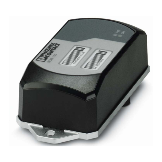
Technical description Technical description Unless otherwise expressly stated, all information provided in this user manual always ap- plies to both the FL WLAN 1100 and the FL WLAN 1101. General description Robust, compact WLAN module with integrated antennas: – Turnkey solution with integrated antenna and wireless module in a single device –... -
Page 8: Fl Wlan 110X Country Registrations
1.2.1 FL WLAN 1100 The FL WLAN 1100 is a WLAN device with access point and client functionality. The device uses the WLAN standard in the license-free 2.4 GHz and 5 GHz bands which are free of charge. It is approved for use in Europe. - Page 9 Cet équipement doit être installé et utilisé avec un minimum de 20 cm de distance entre la source de rayonnement et votre corps. Ce transmetteur ne doit pas etre place au meme endroit ou utilise simultanement avec un autre transmetteur ou antenne. 107390_en_01 PHOENIX CONTACT...
-
Page 10: Firmware
FL WLAN 1000/2000 Firmware Table 1-1 Firmware version Functions FW 1.0x Initial version Additional information on the latest firmware changes for the respective product can be found in the e-shop at phoenixcontact.com or at phoenixcontact.net/product/2702534. PHOENIX CONTACT 107390_en_01... -
Page 11: Mounting/Antenna Configuration
Connections and operating elements of the device Mounting holes Marking fields Status and diagnostic LEDs Ethernet connection in RJ45 format with 100 Mbps Connections for supply voltage and one digital input via COMBICON Two integrated WLAN antennas 107390_en_01 PHOENIX CONTACT... -
Page 12: Housing Dimensions
FL WLAN 1100/1101 2.1.1 Housing dimensions The outside dimensions of the FL WLAN 1100 and FL WLAN 1101 devices are 62.8 mm x 36.5 mm x 113.2 mm (width x height x depth). Figure 2-2 Housing dimensions and distances 2.1.2... -
Page 13: Table 2-1 Connection Data For The Connector
The device must be connected to ground (functional earth ground) via the metal part of the housing. If this is not possible, ensure a low-resistance ground connection (functional earth ground) for the shielding of the Ethernet cable. 107390_en_01 PHOENIX CONTACT... -
Page 14: Mounting The Device On A Level Surface
FL WLAN 1100/1101 FL WLAN 1100 and FL WLAN 1101: it is recommended that the base plate of the device is grounded by connecting the mounting screws to a grounded metal surface (functional earth ground/FE). If this is not possible, e.g., because the device is installed on a plastic surface, you must make sure that the Ethernet cable is properly shielded. -
Page 15: Figure 2-5 Drill Hole Template (Original Size)
Mounting/antenna configuration 2.1.3.1 Drill hole template Figure 2-5 Drill hole template (original size) 107390_en_01 PHOENIX CONTACT... -
Page 16: Mounting The Device With Cable Feed-Through And Seal
The metal cable feed-through (FL M32 ADAPTER, Order No. 2702544) screws into the M32 in- ternal thread of the FL WLAN 1100 connection dome. The FL WLAN 1100 is therefore sealed to IP54 even outdoors. -
Page 17: Figure 2-7 Handling The Fl M32 Adapter
2.1.4.3 Mounting taking the internal antennas into consideration The FL WLAN 1100 has two internal antennas which transmit through the plastic housing. This must be taken into consideration when mounting the device: in order to ensure that the WLAN signal can be transmitted via the built-in antennas, the device must not be installed inside control cabinets or other metal housings. -
Page 18: Figure 2-8 Mounting Distance From Lateral Conductive Surfaces
FL WLAN 1100/1101 In order to optimize the device's performance with respect to transmission, the same rules that apply when mounting antennas should be observed. An important criterion here is the lateral distance from conductive surfaces. These surfaces can influence the radio propaga- tion (directional characteristics of the antenna) due to reflections and interference. -
Page 19: Startup And Configuration
*WLAN connection established (blue): Whether data transmission occurs depends on whether the passwords and certificates are valid. A WLAN connection can therefore exist even if data cannot be transmitted. If WLAN authentication fails, this is indicated in the log file. 107390_en_01 PHOENIX CONTACT... -
Page 20: General Sequence For Startup
FL WLAN 1100/1101 3.1.2 General sequence for startup During startup, supply the device with operating voltage (nominal value: 24 V DC). The as- signment of the connector is shown in Unknown source of cross-reference. In order to start up the device, the device must first be assigned an IP address. This is done via BootP. -
Page 21: Assigning The Ip Address Via Bootp (With Ipassign)
• Click on the “Next” button. Step 3: “IP Address Request Listener” All devices sending a BootP request are listed in the window which opens. These devices are waiting for a new IP address. 107390_en_01 PHOENIX CONTACT... -
Page 22: Figure 3-1 "Ip Address Request Listener" Window
FL WLAN 1100/1101 Figure 3-1 “IP Address Request Listener” window In this example, the device has MAC ID 00.A0.45.04.08.A3. • Select the device to which you want to assign an IP address. • Click on the “Next” button. Step 4: “Set IP Address”... -
Page 23: Reset To The Factory Settings
Figure 3-4 Connection of the supply voltage and the digital input on the bottom of the device 3.1.5.1 Detailed instructions for resetting the device to the factory settings: Connect the device to the supply voltage. 107390_en_01 PHOENIX CONTACT... -
Page 24: Startup Via The Web Interface
FL WLAN 1100/1101 As soon as the device has started up and is ready for operation, you have 1 minute to reset the device to the factory settings. To do this, the digital input must be supplied with voltage equivalent to the operating voltage. The operating voltage must be applied at the digital input for at least 5 seconds. -
Page 25: Quick Setup
PC (for details, see “Assigning the IP address via BootP (with IPAssign)” on page 21). • Using a browser, go to the assigned IP address. • In web-based management, select “Quick Setup”. 107390_en_01 PHOENIX CONTACT... -
Page 26: Figure 3-6 "Login" Web Page
FL WLAN 1100/1101 • Login: enter “admin” as the user name and “private” as the password. Figure 3-6 “Login” web page On the “Quick Setup” page, a wizard guides you through all the relevant parameters for basic configuration. Please note the option on the first page to configure the device from the factory settings (“Factory default”). -
Page 27: Operating Modes Of The Device
For example, for PROFINET applications, it is recommended that the number of clients per access point is reduced to a few devices. This can be achieved by using multiple access points and assign- ing different frequencies and SSIDs. 107390_en_01 PHOENIX CONTACT... -
Page 28: Operating Mode: Client
FL WLAN 1100/1101 3.3.2 Operating mode: Client 3.3.2.1 Compatibility between different WLAN device manufacturers The following describes points relating to the client configuration that should be noted when using WLAN devices from different manufacturers. The Ethernet protocols and the number of Ethernet devices that can be used for transmission are described. - Page 29 In this mode, restrictions apply and not all protocols are transmitted, just Layer 3 trans- parent protocols. This includes, for example, TCP/IP but not PROFINET or Ether- Net/IP™. 3.3.2.4 Operation as a fully transparent bridge (default) Properties: 107390_en_01 PHOENIX CONTACT...
- Page 30 FL WLAN 1100/1101 – Connects several Ethernet devices (connected via Ethernet Switches) to the access point on Layer 2. Connection is only possible with devices (access points) that support the same fully trans- parent bridge mode. – An FTB connection between the FL WLAN 110x and the device (access point) of a third-party manufacturer can only work if the latter uses the same, non-standardized im- plementation.
-
Page 31: Operating Mode: Repeater
Frequency Selection, DFS), depending on the size of the network, the connection may be permanently interrupted. It is recommended that a repeater network is operated at frequencies that do not require DFS, e.g., the 2.4 GHz band. 107390_en_01 PHOENIX CONTACT... -
Page 32: Firmware Update
FL WLAN 1100/1101 Firmware update A firmware update can be performed directly via the web interface. • To do so, select “Update Firmware” under the “System” menu item. • A “Firmware Update” pop-up window allows you to choose whether to update the firm- ware via “HTTP”... -
Page 33: Configuration And Diagnostics Via
The device requires an IP address and a subnet mask in order to access the CLI. The con- figuration of the device network parameters is described in “Assigning the IP address via BootP (with IPAssign)” on page 21. Figure 4-1 Configuration of a Telnet connection in PuTTY Figure 4-2 Initialize a connection with Windows 107390_en_01 PHOENIX CONTACT... -
Page 34: Basic Principles For Using Cli Commands
FL WLAN 1100/1101 Figure 4-3 Command terminal in Windows command prompt Basic principles for using CLI commands In this section, the CLI command names are written in bold. CLI parameters are written in italics and must be replaced by appropriate values (e.g., names or numbers). If a command has several parameters, the order of these must be strictly observed. -
Page 35: Using The Cli Help
Table 4-2 Structure of CLI commands Command Description Display available commands Typing a question mark (?) after each entry displays all the available command names or parameters from this point on. 107390_en_01 PHOENIX CONTACT... -
Page 36: Auto-Completion Of Commands
FL WLAN 1100/1101 If the Help output displays a parameter in angle brackets, this parameter must be replaced by a value. Example: <ipaddr> Enter the IP address If at any point there are no further command names or parameters available or further pa-... - Page 37 The following examples illustrate the correct syntax for entering commands via the CLI Net- work Scripting UI: Example: changing the device name http://192.168.10.42/php/command.php?usr=admin&pwd=private&cmd=device-identity name Device2000 Example: displaying the network parameters and changing the user password http://192.168.10.42/php/command.php?usr=admin&pwd=private&cmd=show network | users passwd private2 107390_en_01 PHOENIX CONTACT...
- Page 38 FL WLAN 1100/1101 PHOENIX CONTACT 107390_en_01...
-
Page 39: Diagnostics
“Interface Status – WLAN” menu. Here, the “Show signal bar” check box must be activated (see Figure 5-2). The check box can only be activated if a con- nection already exists. 7191_en_01 PHOENIX CONTACT... -
Page 40: Figure 5-2 Display Of The Current Signal Strength As A Bar Graph
Measurement is stopped when you exit the web page. Figure 5-2 Display of the current signal strength as a bar graph PHOENIX CONTACT 7191_en_01... -
Page 41: Wlan Channel Assignment Diagnostics In Access Point Mode
If the FL WLAN 1000/2000 is in access point mode, the current WLAN signal strength of up to 10 connected clients (or repeaters) can be displayed. This function can be used to deter- mine the signal strength when setting up wireless paths or when checking the signal strength during operation. 7191_en_01 PHOENIX CONTACT... -
Page 42: Figure 5-4 Display Of The Client Signal Strength At The Access Point
Clicking on the graphic stops the recording procedure and the display is frozen. Figure 5-4 Display of the client signal strength at the access point The value is only displayed and updated while the web page is open. When the web page is closed, the display is cleared. PHOENIX CONTACT 7191_en_01... -
Page 43: Technical Data
Conductor cross section AWG max.: AWG according to UL/CUL min: AWG according to UL/CUL max.: 16 Stripping length 10 mm Note on connection method Recommended conductor cross section: 0.75 mm² Recommended ferrule: connection length 10 Recommended crimping pliers: trapezoidal or square 107390_en_01 PHOENIX CONTACT... -
Page 44: Table 1-1
BootP Wireless interface Antenna connection 2 internal antennas, MIMO, permanently installed Wireless standards for FL WLAN 1100 (Europa ETSI) IEEE 802.11a/b/g/n, up to 300 Mbps Wireless standards for FL WLAN 1101 (USA, Canada FCC/IC) IEEE 802.11a/b/g/1 Wireless modules that can be connected 10 (in Access Point mode max. - Page 45 10g, 16 ms, 6000 shocks 27/IEC 60068-2-27 Broadband noise according to EN 60068-2-64 Category 1, Class A Conformance with EMC directives for the FL WLAN 1100 Noise emission according to EN 55022 Class B Electrostatic discharge (ESD) according to EN 61000-4-2 Contact discharge: ±4 kV...
-
Page 46: Ordering Data
FL CAT5 PATCH 7,5 28 32 61 6 Patch cable, CAT5, pre-assembled, 10.0 m long, 10 pieces FL CAT5 PATCH 10 28 32 62 9 PHOENIX CONTACT GmbH & Co. KG Flachsmarktstr. 8 32825 Blomberg Germany + 49 5235 3-00 + 49 5235 3-41200 www.phoenixcontact.com... - Page 47 “expired”, but it cannot be reused with other parameters under any circum- stances. Phoenix Contact provides notification of ASN1 SNMP objects by publishing their descrip- tions on the Internet. Reading SNMP objects is not password-protected. However, a password is required for read access in SNMP, but this is set to “public”, which is usual for network devices, and can-...
-
Page 48: Figure 6-1 Schematic View Of Snmp
The device supports the following MIBs: MIB II. The full complement of MIB files can be found at www.phoenixcontact.com or MIBs can be downloaded under “Help & Documenta- tion” in web-based management for the device. Up to ten trap receivers can be configured. PHOENIX CONTACT 107390_en_01... - Page 49 List of figures List of figures Figure 1-1: FL WLAN 1100 ..................7 Figure 2-1: Connections and operating elements of the device ......11 Figure 2-2: Housing dimensions and distances ............ 12 Figure 2-3: Connection of the supply voltage, Ethernet, and the reset input ..12 Figure 2-4: Mounting on a level surface ..............
- Page 50 FL WLAN 1100/1101 PHOENIX CONTACT 107390_en_01...
- Page 51 Meaning of diagnostic and status indicators ........19 Table 3-2: Meaning of the icons................24 Table 3-3: Meaning of the buttons ................ 25 Table 4-1: Structure of CLI commands ..............34 Table 4-2: Structure of CLI commands ..............35 107390_en_01 PHOENIX CONTACT...
- Page 52 FL WLAN 1100/1101 PHOENIX CONTACT 107390_en_01...
- Page 53 Mouser Electronics Authorized Distributor Click to View Pricing, Inventory, Delivery & Lifecycle Information: Phoenix Contact 2702538 2702534 2702544...
Need help?
Do you have a question about the FL WLAN 1100 and is the answer not in the manual?
Questions and answers