Phoenix Contact Axioline F User Manual
System and installation
Hide thumbs
Also See for Axioline F:
- User manual (110 pages) ,
- User manual (78 pages) ,
- User manual (44 pages)
Table of Contents
Advertisement
Quick Links
Advertisement
Table of Contents

Related Manuals for Phoenix Contact Axioline F


Summary of Contents for Phoenix Contact Axioline F
- Page 1 Axioline F: system and installation User manual...
- Page 2 UM EN AXL F SYS INST, Revision 07 2018-11-22 This user manual is valid for:: All modules of the Axioline F product group without bus-specific special features. PHOENIX CONTACT GmbH & Co. KG • Flachsmarktstraße 8 • 32825 Blomberg • Germany phoenixcontact.com...
- Page 3 Documentation on the Internet ................11 Purpose of this user manual ................11 The Axioline F product group....................13 Axioline F – the block-based modular I/O system ..........13 Features ......................13 Structure of an Axioline F station ................. 15 Product description....................16 Approvals ......................
- Page 4 Mounting distances ..................... 62 Connecting or removing cables ....................65 Connections and cables in the Axioline F system ..........65 Conductor cross sections and stripping and insertion lengths ......66 Terminal point, associated spring lever, and associated touch connection ..68 Connecting unshielded cables ................
- Page 5 Shielding with Axioline F ..............87 8.2.2 Shielding when connecting analog sensors and actuators ....87 8.2.3 Connecting the shield using the Axioline F shield connection set ..88 8.2.4 Connecting the shielding to a busbar ........... 92 8.2.5 Integrating analog shielding in a concept with central equipotential bonding at the control cabinet entry .............
- Page 6 12.2 Ordering data ....................114 Technical appendix.........................119 Use of Axioline F modules at an elevation of more than 3000 meters....119 Transmission speed ..................120 Typical cycle time on the local bus ..............120 Response times for an Axioline F system ............121 Communication objects (PDI objects)...............
- Page 7 Intended use Axioline F controllers, Axioline F bus couplers, and Axioline F I/O modules should only be used according to the instructions in the module-specific documentation and this user manual. Phoenix Contact accepts no liability if the modules are used for anything other than their designated use.
- Page 8 Modifications to hardware and firmware of the device are not permitted. Incorrect operation or modifications to the device can endanger your safety or damage the device. Do not repair the device yourself. If the device is defective, please contact Phoenix Contact. 8 / 148 PHOENIX CONTACT...
-
Page 9: Axioline F Documentation
Documentation landscape of Axioline F Available documents The documentation for the Axioline F product group is modular, providing you with the optimum information to meet your requirements. In the following table, the term module describes the controller, bus coupler, and I/O module. - Page 10 UM EN AXL F SYS INST Table 2-1 Axioline F documentation [...] Document Contents Additional: information on a specific module Additional user manuals The additional user manuals either describe: – A bus coupler connected to a network or – A specific module Each manual only describes the relevant module and/or bus-specific special fea- tures.
- Page 11 Comprehensive documentation can be found in the download area for the bus coupler. Purpose of this user manual This user manual informs you about the Axioline F system. It describes the system and everything about Axioline F module mounting and wiring regardless of a higher-level network.
- Page 12 UM EN AXL F SYS INST 12 / 148 PHOENIX CONTACT 7982_en_07...
- Page 13 In addition, the control quality and as a result the product quality increases thanks to the fast signal processing feature. Axioline F is as fast as parallel cabling, so the speed for data transmission is determined by the higher-level network. –...
- Page 14 Transmission speed in the local bus 100 Mbps – Communication to the higher-level system via an Ethernet-based protocol (e.g., ® PROFINET, Sercos, EtherCAT , Modbus/TCP) – Very good diagnostic properties for the Axioline F system and the application 14 / 148 PHOENIX CONTACT 7982_en_07...
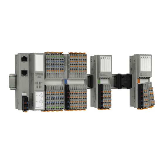
- Page 15 The Axioline F product group Structure of an Axioline F station An Axioline F station consists of individual modules, which are snapped onto a DIN rail. A controller or a bus coupler forms the head of the station. I/O modules are mounted next to Bus base modules are used for the connection of the individual modules to one another and to the station head.
- Page 16 Product description Modules with various functions are available within the Axioline F product group. The Axioline F modules consist of an electronics module, one or several connectors, and a bus base module. The electronics module can be changed without having to remove a wire from the connector.
-
Page 17: Voltage Ranges For Axioline F
Section “Safety notes for mounting and removal” on page Mounting location The Axioline F modules meet IP20 degree of protection and can be used in closed control cabinets or in control boxes (junction boxes) with IP54 degree of protection according to EN 60529 or higher. - Page 18 UM EN AXL F SYS INST Axioline F local bus There is an interface to the Axioline F local bus on the bottom of the modules. Bus base modules are used to carry the communications power and the bus signals from the controller or bus coupler through the Axioline F station.
- Page 19 The Axioline F product group Diagnostics The Axioline F system provides comprehensive diagnostics: – Remote diagnostics – Process diagnostics (e.g., cycle time monitoring) – Communication diagnostics – Module diagnostics (status of Axioline F module) – I/O diagnostics (status of sensors/actuators) For the diagnostic options of a specific module, please refer to the module-specific data sheets.
- Page 20 Enter the order designation, a part of it, or the order number in the search window. Figure 3-3 Searching for order number 2688310 • Select the product. • Switch to the “Approvals” tab. The current approvals of the product are listed. Figure 3-4 Current approvals of product 2688310 20 / 148 PHOENIX CONTACT 7982_en_07...
-
Page 21: Selecting Gl Approval
The Axioline F product group Searching for all products When searching for products that have a specific approval, e.g., GL or ATEX-approved that have a specific products, please proceed as follows: approval • Enter AXL F, for example, in the search window. - Page 22 UM EN AXL F SYS INST 22 / 148 PHOENIX CONTACT 7982_en_07...
- Page 23 Overview of Axioline F modules Overview of Axioline F modules Axioline F order designation The order designation helps you to identify the function of a module. Product Function and number Conduc- Function Housing group of inputs or outputs tor con-...
- Page 24 UM EN AXL F SYS INST Table 4-1 Structure of the order designations Product group AXL F Axioline F Axiocontrol for the direct control of Axioline F I/Os AXC F PLCnext Control for direct control of Axioline F I/Os Function Bus coupler Digital input...
- Page 25 Overview of Axioline F modules Table 4-1 Structure of the order designations [...] Function extensions 1xxx Performance class 1000 3xxx Performance class 3000 (for controllers) 2152 Performance class 2000 Function extension High speed Extreme conditions (extreme ambient conditions) (for other modules)
- Page 26 Example: AXC 1050, AXC 3050, and AXC F 2152 A controller is a modular control system with integrated Ethernet and Axioline F local bus connection. As the head of an Axioline F station, the controller provides the function of a control system.
-
Page 27: Example: Axl F Bk Pb
Figure 4-2 Example: AXL F BK PB With a network and an Axioline F local bus connection, the bus coupler is the head of an Axioline F station and represents the link between your network and the Axioline F station. - Page 28 Safety modules with safe digital inputs or outputs (PSDI, PSDO, Section “Safety modules with safe digital inputs or outputs” on page – Power module for the communications power U (see Section “Power module for the communications power U Bus” on page 30 – 28 / 148 PHOENIX CONTACT 7982_en_07...
-
Page 29: Temperature Change Cycle
– The Axioline F station was not exposed to vibration or shock – The Axioline F station was operated with a maximum of 24.5 V (ensured by using electronically regulated power supply units) 3 h + 30 min (3 0,6) K/min... - Page 30 4.4.3 Safety modules with safe digital inputs or outputs The safety modules are to be used in an Axioline F station at any point in a safe system (e.g., PROFIsafe). Depending on the version, the modules either have safe digital inputs or outputs. They can be parameterized according to the specific application, and enable the integration of sensors and actuators in the safe system.
- Page 31 Housing versions, design, and dimensions Housing versions, design, and dimensions Housing versions Various housing versions are available in the Axioline F portfolio; they are shown in Figure 5-1. AXC 3 AXC F 2xxx 1F (LV5) 1F (LV4) 1F (PM) 1H (S)
- Page 32 AXL SSI 1/AO 1 Figure 5-13 on page 39 1H (UNI) Universal AXL F PWR 1H Figure 5-14 on AXC F XT IB 1H page 39 AXL F DO16 FLK 1H Figure 5-15 on page 40 32 / 148 PHOENIX CONTACT 7982_en_07...
- Page 33 Housing versions, design, and dimensions Basic design of Axioline F modules 5.2.1 Class 3000 AXC controller Figure 5-2 Design of an AXC 3050 controller Bus base module Electronics module Ethernet interfaces Function identification and FE tab: A 2.8 mm FE tab for optional functional ground connection is located under the function...
- Page 34 Bus base module Electronics module Reset button SD card holder (the SD card is optional and not supplied as standard) Diagnostic and status indicators Ethernet interfaces Supply connector (connector for connecting the communications power U 34 / 148 PHOENIX CONTACT 7982_en_07...
- Page 35 There are two FE springs on the bottom of the module for connecting the functional ground via the DIN rail. These are not shown in Figure 5-4. They are illustrated in Figure 8-1 on page 35 / 148 7982_en_07 PHOENIX CONTACT...
- Page 36 There is at least one FE spring on the bottom of the module for connecting the functional ground via the DIN rail. This is not shown in Figure 5-5. It is illustrated in Figure 8-1 on page 36 / 148 PHOENIX CONTACT 7982_en_07...
-
Page 37: Nominal Dimensions Of A Class 3000 Axc Controller Housing
Housing versions, design, and dimensions Axioline F module dimensions 5.3.1 AXC controller and bus coupler Figure 5-6 Nominal dimensions of a class 3000 AXC controller housing (type AXC 3, e.g., AXC 3050, AXC 3051) Figure 5-7 Nominal dimensions of a class 2000 AXC controller housing (type AXC F, e.g., AXC F 2152) -
Page 38: Nominal Dimensions Of The F Housing With Two Terminal Fields
Nominal dimensions of the F housing with one terminal field (type 1F, e.g., AXL F AI8 XC 2H, AXL F DI32/1 2H) Figure 5-11 Nominal dimensions of the H housing with two terminal fields (type 2H, e.g., AXL F DI16/1 DO16/1 2H) 38 / 148 PHOENIX CONTACT 7982_en_07... -
Page 39: Figure 5-12 Nominal Dimensions Of The H Housing With One Terminal Field
(type 1H (S), e.g., AXL F SSI1 AO1 1H) Figure 5-14 Nominal dimensions of the H housing with one terminal field and short connectors (type 1H (UNI), e.g., AXL F PWR 1H, AXC F XT IB 1H) 39 / 148 7982_en_07 PHOENIX CONTACT... -
Page 40: Figure 5-15 Nominal Dimensions Of The H Housing With One Terminal Field And Short Connectors (Type 1H (Uni), Axl F Do16 Flk 1H)
53,6 Figure 5-17 Nominal dimensions of the F housing for the low voltage area with one terminal field and four connectors (type 1F-LV4, e.g., AXL F DI8/2 110/220DC 1F, AXL F DOR4/2 AC/220DC 1F) 40 / 148 PHOENIX CONTACT 7982_en_07... -
Page 41: Figure 5-18 Nominal Dimensions Of The F Housing For Power Measurement With One Terminal Field (Type 1F-Pm, Axl F Pm Ef 1F)
Housing versions, design, and dimensions 5.3.4 Power measurement module 53,6 65,5 Figure 5-18 Nominal dimensions of the F housing for power measurement with one terminal field (type 1F-PM, AXL F PM EF 1F) 41 / 148 7982_en_07 PHOENIX CONTACT... -
Page 42: Figure 5-19 Bus Base Modules
Bus base modules carry the communications power and the bus signals from the bus coupler or the controller through the Axioline F station (local bus). A bus base module is supplied as standard with each controller, bus coupler, and Axioline F module. -
Page 43: Figure 5-21: Connectors: Versions And Dimensions
Housing versions, design, and dimensions Axioline F connectors The Axioline F connectors accept cables up to 1.5 mm and a stripping length of 8 mm. Detailed information on the conductor cross section and stripping lengths can be found in Section “Conductor cross sections and stripping and insertion lengths” on page 5.5.1... -
Page 44: Figure 5-22 Basic Design Of An Axioline F Connector
UM EN AXL F SYS INST 5.5.2 Basic design Figure 5-22 Basic design of an Axioline F connector Local diagnostic and status indicators Terminal point Touch connection Terminal point marking Spring lever The color of the spring lever corresponds to the function (see Section “Color and... -
Page 45: Figure 5-23 Color Coding Of The Module Function
Pale green RAL 6021 Analog input, temperature measurement Zinc yellow RAL 1018 Analog output Pastel orange RAL 2003 Function: open and closed-loop control, communi- cation, position detection Pure white RAL 9010 Bus coupler, controller, boost 45 / 148 7982_en_07 PHOENIX CONTACT... -
Page 46: Figure 5-24 Marking Of The Terminal Points And The Leds On The Connectors
UM EN AXL F SYS INST Connections Apart from the Axioline F connectors, all connections are consecutively numbered, e.g., X1, X2 for Ethernet connections. Operating elements Operating elements are marked according to their function, e.g., rotary coding switches with S1 and S2 including the switch positions. -
Page 47: Figure 5-25: Individual Marking Options
114. Slot and connector Each slot on the module and the associated connector can be marked individually to ensure marking clear assignment between the slot and the connector (1 and 3 in Figure 5-25). 47 / 148 7982_en_07 PHOENIX CONTACT... - Page 48 UM EN AXL F SYS INST 48 / 148 PHOENIX CONTACT 7982_en_07...
- Page 49 Switch off the I/O supply voltage at the relevant module. The communications power that is supplied at the bus coupler or controller is still available. For a bus coupler or controller, this means: Disconnect the communications power supply at the bus coupler or controller. 49 / 148 7982_en_07 PHOENIX CONTACT...
-
Page 50: Figure 6-1 Placing And Removing The Module Vertically
Placing and removing the module vertically When using modules in the low voltage area, please also observe Section “Additional safety notes for the low voltage area” on page Additionally observe the information in the module-specific data sheets. 50 / 148 PHOENIX CONTACT 7982_en_07... - Page 51 • The Axioline F modules for the low voltage area must only be operated in a closed control cabinet. Failure to observe these instructions can lead to damage to health or even life-threatening injury.
-
Page 52: Figure 6-2: Fixing The Din Rail (In Mm)
DIN rail All Axioline F modules are mounted on 35 mm standard DIN rails. The preferred height of the DIN rail is 7.5 mm (corresponds to TH 35-7.5 according to EN 60715). The recommended DIN rails from Phoenix Contact or recommended mounting straps from Lütze can be found in... -
Page 53: Figure 6-3 Mounting Positions For An Axioline F Station
Figure 6-3). The end brackets ensure that the Axioline F station is correctly mounted. End brackets secure the station on both sides and keep it from moving from side to side on the DIN rail. Always attach the left end bracket of the station when beginning to mount the station. This ensures the following: –... - Page 54 Maximum number of The maximum number of Axioline F modules within a station is 63. modules The actual number of modules within an Axioline F station may be limited by the following factors: – Supplied logic current –...
- Page 55 They are provided with the product upon delivery. Mounting the modules Please refer to Section “Safety notes for mounting and removal” on page No tools are required for mounting the Axioline F modules. • First mount the end bracket on the DIN rail. 55 / 148...
-
Page 56: Figure 6-4: Connecting Bus Base Modules To Each Other
Make sure that the device connector for the bus base connection is positioned above the corresponding female connector on the bus base module. Figure 6-5 Snapping on the bus coupler Connecting the network Connect the network according to the specifications in the module-specific documentation. 56 / 148 PHOENIX CONTACT 7982_en_07... -
Page 57: Figure 6-6 Inserting I/O Modules
Inserting I/O modules If you are using analog modules, mount the necessary shield connection elements. For connecting the shield, Phoenix Contact recommends the AXL SHIELD SET Axioline F shield connection set or the shield connection clamp products from the “Installation and mounting material, grounding, and shielding”... - Page 58 The cables should only be removed from the connector if you wish to change the wiring or no longer wish to use the connector. Removing cables Section “Removing cables from the terminal point” on page Removing the Axioline F Section “Removing or inserting a connector” on page connectors 58 / 148...
-
Page 59: Figure 6-7 Removing The Bus Coupler
Insert a suitable tool (e.g., bladed screwdriver) into the latches on one side (B, B1, B2) one after the other. • Swivel the bus base module upward and remove it (C). Figure 6-9 Removing the bus base module 59 / 148 7982_en_07 PHOENIX CONTACT... - Page 60 • Swivel the bus base module upward and remove it (C). • Push the rest of the station back to the left until the bus base modules touch each other again. 60 / 148 PHOENIX CONTACT 7982_en_07...
-
Page 61: Figure 6-10 Removing The Connector
To replace a module, proceed as described in Sections “Removing modules” on page 58 “Mounting the modules” on page • Once replaced, restore all of the necessary connections. When replacing a controller: Observe any notes for replacement in the module-specific documentation. 61 / 148 7982_en_07 PHOENIX CONTACT... -
Page 62: Figure 6-12 Mounting Distances: Axc 305X Controller (Dimensions Rounded)
In addition to the specified dimensions, provide adequate space for mounting and removal of the connectors and cables. Figure 6-12 Mounting distances: AXC 305x controller (dimensions rounded) Figure 6-13 Mounting distances: bus coupler and AXC 105x controller (dimensions rounded) 62 / 148 PHOENIX CONTACT 7982_en_07... -
Page 63: Figure 6-14 Mounting Distances: I/O Modules (Dimensions Rounded)
Mounting and removing modules Figure 6-14 Mounting distances: I/O modules (dimensions rounded) If the distances are smaller, the minimum bending radius of the cables, easy handling during installation, and a clear structure cannot be assured. 63 / 148 7982_en_07 PHOENIX CONTACT... - Page 64 UM EN AXL F SYS INST 64 / 148 PHOENIX CONTACT 7982_en_07...
- Page 65 The network cables on the controller or bus coupler are connected via the D-SUB or RJ45 connectors depending on the network. The cables for the I/O devices and supply voltages are connected using Axioline F connectors. Each terminal point is designed for a maximum current of 8 A. This applies to the periphery of the I/O modules (I/O connectors) as well as to the supply of the logic, sensors, and actuators (power connectors).
-
Page 66: Permissible Conductor Cross Sections For Push-In Connection Technology (Without Using The Spring Lever For Inserting The Conductor)
Stranded with ferrule without insulating collar (A ...) 0.25 mm ... 1.5 mm Stranded with ferrule with insulating collar (AI ...) 0.25 mm ... 1.5 mm Table 7-3 Permitted AWG conductor cross sections Conductor Cross section 24 ... 16 66 / 148 PHOENIX CONTACT 7982_en_07... - Page 67 Section “Ordering data for accessories” on page 114). According to the current state, only these pliers meet the general conditions regarding the Axioline F wiring space (according to internal cylindrical gauge DIN EN 60947-1 (DIN VDE 0660-100)-A1). Conductor without ferrule: stripping length 8 mm...
-
Page 68: Figure 7-1 Terminal Point With Associated Spring Lever, And Associated Touch Connection
Cable outlet at the bottom: Spring lever and touch connection above the ter- minal point Cable outlet at the top: Spring lever and touch connection below the ter- minal point (B) Terminal point Spring lever Touch connection 68 / 148 PHOENIX CONTACT 7982_en_07... -
Page 69: Figure 7-2: Connecting A Solid Unshielded Cable
Open the spring by pressing the screwdriver onto the spring lever (Figure 7-3, A). Use, for example, a bladed screwdriver with a blade width of 2.5 mm. Phoenix Contact recommends the SZS 0,4x2,5 screwdriver (see Section “Ordering data” on page 114). -
Page 70: Figure 7-4: Inserting The Connector
The busbar is only for shielding the module, not for the strain relief of the connected cables. Wiring the connector • Connect the cables to the connector. Please proceed as described in Section “Connecting unshielded cables” on page 70 / 148 PHOENIX CONTACT 7982_en_07... -
Page 71: Figure 7-6 Removing The Cable
(e.g., bladed screwdriver with a blade width of 2.5 mm). This opens the leg-spring connection of the relevant terminal point (Figure 7-6, A). • Remove the conductor (Figure 7-6, B). Figure 7-6 Removing the cable 71 / 148 7982_en_07 PHOENIX CONTACT... -
Page 72: Figure 7-7 Supply Voltages In The Axioline F System
UM EN AXL F SYS INST Connecting the power supplies 7.7.1 Axioline F system supply When using an Axioline F station you must provide the following supply voltages: – Supply voltage for the bus coupler – Supply voltage for the local bus (communications power of the connected modules) –... - Page 73 7.7.4 Supply at the power module If the maximum load of the bus coupler for the Axioline F local bus supply (communications power U ) is reached, you can use a power module to provide this voltage again.
-
Page 74: Figure 7-8 Jumpering In The Power Connector And Example Of Potential Forwarding
Considering the current carrying capacity of the terminal points, potential forwarding shown in Figure 7-8 must not be used when the digital output module is fully loaded (e.g., AXL F DO16/3 2F current consumption at U is 8 A, maximum). 74 / 148 PHOENIX CONTACT 7982_en_07... -
Page 75: Figure 7-9 Parallel Supply Of The Supply Voltage
8 A max. 8 A Figure 7-9 Parallel supply of the supply voltage Connecting the network Your network cable is connected to a controller or bus coupler. Connect the network according to the module-specific documentation. 75 / 148 7982_en_07 PHOENIX CONTACT... -
Page 76: Figure 7-10 Connecting Cable Between Pc And Controller Or Bus Coupler
1000 controllers. To use the programming interface, a corresponding driver must be installed. It is provided with the software tools from Phoenix Contact. A connecting cable (CAB-USB A/MICRO USB B/2,0M, Order No. 2701626) is required for direct connection of the controller or bus coupler to a PC via the programming or service interface. - Page 77 7.10.1 Connection technology for sensors and actuators The I/O modules of the Axioline F product group normally permit connection of sensors and actuators in 1, 2, 3 or 4-wire technology. The relevant module-specific data sheets indicate which connection technology is possible for the individual modules.
-
Page 78: Overview Of The Connections Used For Low-Level Signal Digital Input Modules
Overview of the connections used for low-level signal digital output modules Connection Representation in the 1-wire 2-wire 3-wire figure Actuator signal OUT Actuator supply U (+24 V) – – – Ground GND – Grounding/FE shielding FE ( – – Used – Not used 78 / 148 PHOENIX CONTACT 7982_en_07... -
Page 79: Figure 7-11 1-Wire Termination For Digital Modules
The load is switched directly via the output. NOTE: Malfunction To ensure the correct function, make sure that GND of the actuators and GND of the supply voltage U , which supplies the actuators, have the same potential. 79 / 148 7982_en_07 PHOENIX CONTACT... -
Page 80: Figure 7-12 2-Wire Termination For Digital Modules
7-13, B, shows the connection of a shielded actuator. – The actuator is supplied by output OUT1. – The load is switched directly via the output. – The actuator is grounded via the FE terminal point. 80 / 148 PHOENIX CONTACT 7982_en_07... -
Page 81: Figure 7-14 4-Wire Termination For Digital Modules
4-wire sensor. – The sensor signal is routed to terminal point IN1. – The sensor is supplied with power via terminal points U and GND. – The sensor is grounded via the FE terminal point. 81 / 148 7982_en_07 PHOENIX CONTACT... -
Page 82: Figure 7-15 Connection Of Relay Modules
Figure 7-15 Connection of relay modules Figure 7-16 Connection of a termination board For accessories, please refer to the module-specific data sheet. 82 / 148 PHOENIX CONTACT 7982_en_07... -
Page 83: Figure 7-17: Example: Connection For Redundant Use Of Digital Inputs
7.10.5 Redundant signals If you are using I/O modules redundantly, connect the modules as shown in Figure 7-17. In the example, the two modules are located in two Axioline F stations. 7.10.5.1 Redundant digital inputs IN08 24 V DC Figure 7-17... -
Page 84: Figure 7-18: Example: Connection For Redundant Use Of Digital Outputs
Figure 7-18 established as the reference potential to the redundant signal outputs. Make sure that, in the event of a short circuit of the supply, the effects are limited by providing decoupling (longitudinal diode). 84 / 148 PHOENIX CONTACT 7982_en_07... - Page 85 Grounding and shielding Grounding and shielding Grounding concept Within an Axioline F station, a distinction is made between functional ground (FE) and protective earth ground (PE). Protective earth Protective earth grounding protects people and machines against hazardous voltages. To grounding (PE) avoid these dangers as far as possible, correct grounding, taking the local conditions into account, is vital.
-
Page 86: Figure 8-1: Fe Spring (1)
Do not connect the functional ground of the modules for surge protection to an Axioline F module (e.g., to an FE contact of an Axioline F connector). This ensures that interference is discharged before it enters the Axioline F module. - Page 87 Grounding and shielding Shielding concept Shielding is used to reduce the effects of interference on the system. 8.2.1 Shielding with Axioline F In the Axioline F system, shielded cables are used with the following modules: – Network cables – Connecting cables –...
-
Page 88: Figure 8-2 Connecting The Shield With Axl Shield Set
The shield connection set consists of two busbar holders and two SK 5 shield connection clamps. This shield connection set can be used to connect cable shields in an Axioline F station in the vicinity of the modules. -
Page 89: Figure 8-3 Set Components
If using a busbar holder at the end of an Axioline F station, mount the busbar holder after the last module. In this case, it is not positioned above a bus base module. Secure the busbar holder using an end bracket (accessories). -
Page 90: Figure 8-5 Snapping On The Busbar Holders
Snapping on the busbar holders • Push the busbar into the busbar holders. • Secure the busbar using the SK 5 shield connection clamps included in the scope of supply. Figure 8-6 Mounting the busbar 90 / 148 PHOENIX CONTACT 7982_en_07... -
Page 91: Figure 8-7: Mounting The Electronic Modules
DIN rail. • Remove the busbar holder. Figure 8-8 Removing the shield connection The locking clip may become deformed following contact with the screwdriver. In this case, bend it back into shape prior to reassembly. 91 / 148 7982_en_07 PHOENIX CONTACT... -
Page 92: Figure 8-9: Connecting The Shielding To A Busbar
Connect the shield for the entire analog transmission path to FE potential at only one point. In this example, this point is the busbar. Busbar Lead the sensor cable into the sensor, making sure to maintain the cable insulation. 92 / 148 PHOENIX CONTACT 7982_en_07... -
Page 93: Figure 8-10 Integration Of Analog Shielding In A Concept With Central Equipotential Bonding At The Control Cabinet Entry
Observe the following when integrating the shielding of analog I/O cables in an equipotential bonding concept: Direct connection to the FE potential must only be made at one point (e.g., at the central grounding point of the marshaling level). 93 / 148 7982_en_07 PHOENIX CONTACT... - Page 94 UM EN AXL F SYS INST 94 / 148 PHOENIX CONTACT 7982_en_07...
- Page 95 Diagnostic and status indicators Diagnostic and status indicators All Axioline F modules are provided with diagnostic and status indicators for quick local error diagnostics. They enable the clear localization of system errors (bus errors) or I/O errors. Diagnostics The diagnostic indicators (red, yellow, or green) provide information on the state of the module.
- Page 96 Firmware/bus coupler is booting. Flashing Firmware update is being performed. yellow Flashing Firmware update has failed. yellow/red Flashing Faulty firmware Red on Rotary encoding switches are set to an invalid/reserved position. Device is not ready to operate. 96 / 148 PHOENIX CONTACT 7982_en_07...
- Page 97 No I/O messages present Further diagnostic and/or status indicators may also be available. For the diagnostic and status indicators on the bus coupler and their meanings, please refer to the documentation for the bus couplers. 97 / 148 7982_en_07 PHOENIX CONTACT...
- Page 98 Yellow on Warning (priority 2) Red/yel- I/O error or channel error or warning (group message) Indicates messages that only apply to a single channel. Red on Error (priority 1) Yellow on Warning (priority 2) 98 / 148 PHOENIX CONTACT 7982_en_07...
- Page 99 Output Supply for digital input and output modules Input/Output Supply for analog modules Analog For information about the diagnostic and status indicators on a module and their meaning, please refer to the module-specific documentation. 99 / 148 7982_en_07 PHOENIX CONTACT...
-
Page 100: Leds On The I/O Connector
The malfunctions indicated by the local diagnostic and status indicators are also mapped in PDI object 0018 (DiagState). Detailed information can be found in Section “Objects for diagnostics” on page 127 and in the module-specific data sheet. 100 / 148 PHOENIX CONTACT 7982_en_07... - Page 101 10.1 Process data Axioline F devices have at least eight bits of process data. If less than eight bits are used, they occupy the least significant bits of the byte. The significance of the data corresponds to the Motorola format (Big Endian).
- Page 102 Every service access consists of a request and the associated confirmation. Only one service can be processed for an I/O module at a time. The service structure depends on the higher-level system. For more information, please refer to your system documentation. 102 / 148 PHOENIX CONTACT 7982_en_07...
- Page 103 10.3 Saving of parameters Every Axioline F module has parameters. They can be read or written or can be read and written. The parameters that can be written are saved every time a change is made. Some parameters are defined as startup parameters in the device description file of each module.
- Page 104 UM EN AXL F SYS INST 104 / 148 PHOENIX CONTACT 7982_en_07...
- Page 105 – PLCnext Engineer You can also integrate Axioline F into any other system, e.g., via GSDML in STEP 7 or via DTM (Device Type Manager) in FDT framework applications. For the software for supporting safety modules, please refer to the module-specific documentation.
- Page 106 Detailed online help for the documentation of software functions Startup+ and the device-specific DTM can be downloaded at phoenixcontact.net/products. Here you will also find a quick start guide for using the Axioline F station under Startup+. 106 / 148 PHOENIX CONTACT...
- Page 107 11.4.1 PC Worx Axioline F is supported by “AX SW Suite” 1.50, Service Pack 3 or later. PC Worx is the consistent engineering software for all controllers from Phoenix Contact. It combines programming according to IEC 61131, fieldbus configuration for INTERBUS, PROFINET, and Modbus, as well as system diagnostics –...
- Page 108 UM EN AXL F SYS INST 108 / 148 PHOENIX CONTACT 7982_en_07...
- Page 109 For the system data of your network, please refer to the corresponding documentation. If you are using Axioline F in a system with other product groups, also observe the technical data for these product groups. For this technical data, please refer to the associated documentation.
- Page 110 Criterion A Fast transients (burst) EN 61000-4-4/IEC 61000-4-4 Criterion B Transient overvoltage (surge) EN 61000-4-5/EN 61000-4-5 Criterion B Conducted interference EN 61000-4-6/IEC 61000-4-6 Criterion A Noise emission test according to EN 61000-6-3 Class B 110 / 148 PHOENIX CONTACT 7982_en_07...
- Page 111 EN 61000-4-16/IEC 61000-4-16 Attenuated oscillating waves EN 61000-4-18/IEC 61000-4- 1 kV symmetrical, 2.5 kV asymmetrical Radio disturbance characteristics EN 55022 Class B Interface for Axioline F local bus Connection method Bus base module Transmission speed 100 Mbps 111 / 148...
- Page 112 The Axioline F local bus supply (communications power) U is generated from communications power U (24 V). Axioline F local bus supply (supplies the bus logic of the connected modules) Comment The communications power U is supplied on the bus cou- pler, controller or power module for the communications power.
- Page 113 Technical data and ordering data Axioline F connector/connection method/cable cross sections For electrical and/or thermal reasons, it may not be possible to use the minimum conductor cross sections specified here for certain modules. Therefore, always observe the information in the module-specific docu- mentation.
- Page 114 The complete product catalog is available in electronic form at phoenixcontact.net/products. Ordering data for the Axioline F modules For the ordering data for the Axioline F modules, please refer to the module-specific documentation. It is also available on the Internet at phoenixcontact.net/products.
- Page 115 USLKG 5 0441504 connection, cross section: 0.2 mm² - 6 mm², AWG 24 - 10, width: 6.2 mm, color: green-yellow, mounting type: NS 35/7.5, NS 35/15, NS 32 (can be used as end bracket) 115 / 148 7982_en_07 PHOENIX CONTACT...
- Page 116 Cross section 0.5 mm A 0,5 -10 3202494 1000 Cross section 0.75 mm A 0,75-10 3200234 1000 Cross section 1.0 mm A 1 -10 3200250 1000 Cross section 1.5 mm A 1,5 -10 3200276 1000 116 / 148 PHOENIX CONTACT 7982_en_07...
- Page 117 2901605 FLK14/AXIO/0,14/1,0M Additional cable lengths VIP-CAB-FLK14/AXIO/0,14/ Connecting cable Connecting cable for connecting the controller to a PC for CAB-USB A/MICRO USB 2701626 PC Worx, USB A to micro USB B, length: 2 m B/2,0M 117 / 148 7982_en_07 PHOENIX CONTACT...
- Page 118 UM EN AXL F SYS INST Ordering data for documentation Description Type Order No. Pcs./Pkt. “Axioline F: diagnostic registers, and error messages” user UM EN AXL F SYS DIAG – – manual The comprehensive documentation listed above and all module-specific documentation can be downloaded at phoenixcontact.net/products.
- Page 119 – XC versions In these cases, consider the individual module or application separately. The Axioline F modules are approved for use up to an elevation of 3000 m above sea level, “Technical data” on page 109. The maximum permissible ambient temperature decreases at elevations above this level.
- Page 120 UM EN AXL F SYS INST Transmission speed Within an Axioline F station, communication takes place via a fast, cyclic and equidistant local bus. The typical cycle time is less than 50 µs. Typical cycle time on the local bus The typical cycle time on the local bus is calculated according to the following equation: t = 2 µs + n * 1 µs...
- Page 121 Response times for an Axioline F system Response times for an Axioline F system In general, the response time for an I/O system is the time from reading in the input, processing in the controller to setting the output. This includes: –...
-
Page 122: Typical Processing Times In The Overall System (Example)
6 Controller cycle time 1 ms The example clearly shows that when determining the response time of the overall system, Axioline F represents the smallest proportion by far and therefore can normally be ignored. Explanation of terms Conversion time Signal runtime of the Axio protocol in an Axioline F mod- Input filter time (e.g., RTD) -
Page 123: Object Types
Value without prefix sign, only positive values 00 ... FF Unsigned 16 UINT16 Value without prefix sign, only positive values 0000 ... FFFF Unsigned 32 UINT32 Value without prefix sign, only positive values 0000 0000 ... FFFF FFFF 123 / 20 7982_en_07 PHOENIX CONTACT... -
Page 124: Objects For Identification (Device Rating Plate) According To Basic Profile V3.0
The bold entries in Table A-5 are identical for all Axioline F modules from Phoenix Contact. All other entries may vary depending on the individual module. Table A-5 Objects for identification (device rating plate) according to basic profile V3.0... - Page 125 .2 Version Visible string Version ID xxx (e.g., 2016-12-01, PDI V1.10) 0037 DeviceType Octet string Device type xx xx xx xx xx xx xx xx (e.g., 00 20 00 08 00 00 00 A6 125 / 20 7982_en_07 PHOENIX CONTACT...
- Page 126 The slave is a subbus master. There is at least one additional subsystem below this slave. FwUpdt0 The slave supports the firmware update. SyncI_0 The slave supports synchronization of the inputs. SyncO_0 The slave supports synchronization of the outputs. 126 / 20 PHOENIX CONTACT 7982_en_07...
-
Page 127: Objects For Diagnostics: Diagnostic State (Read) According To Basic
.4 Code Octet string Error code .5 MoreFollows Bit string 8 Additional information on malfunction; not used with Axioline F up to now .6 Text Visible string 51, max. Plain text message. Default: status OK Table A-8 Objects for diagnostics: diagnostic state (read) according to basic profile V3.x... - Page 128 They can be read via the E806 “ComplDiagState” object. Bit 5 ... 6 Reserved Bit 7 Indication that this is an extended version of object 0018 (com- pared to the version from basic profile V2.x). 128 / 20 PHOENIX CONTACT 7982_en_07...
-
Page 129: Objects For Diagnostics: Acknowledge Diagnostic Messages (Write)
A 5.4 Value ranges Make sure to observe the permissible value ranges during module parameterization. If invalid values are specified for an object, these are not saved and an error message is generated. 129 / 20 7982_en_07 PHOENIX CONTACT... - Page 130 The higher-level network is the communication system which links the controller and the head of the Axioline F station. This network must support synchronization. The head of an Axioline F station can be a bus coupler or an AXC controller. Currently, only some bus couplers support synchronization.
-
Page 131: Synchronization Mechanisms Of The Bus Couplers
Synchronization Bus coupler The bus coupler is the link between the higher-level network and the Axioline F station. It must support synchronization according to the definition of the higher-level network and transfer the synchronization parameters and signals to the Axioline F station. -
Page 132: Synchronization Options
To make good use of this function, the following conditions must be met: The higher-level controller must support synchronization mechanisms for the network. The bus coupler must support synchronization mechanisms for the network. At least one module on the local bus must support local bus synchronization. 132 / 20 PHOENIX CONTACT 7982_en_07... - Page 133 Power-on behavior The power-on behavior defines the module behavior after switching on the power supply. An Axioline F module has this behavior until it receives valid process data. Substitute value behavior (failsafe behavior) The substitute value behavior defines the module behavior when process data is missing.
- Page 134 UM EN AXL F SYS INST 134 / 20 PHOENIX CONTACT 7982_en_07...
-
Page 135: Table Of Contents
Section 3 Figure 3-1: Example of an Axioline F station ............15 Figure 3-2: Components of an Axioline F I/O module ..........16 Figure 3-3: Searching for order number 2688310 ..........20 Figure 3-4: Current approvals of product 2688310 ..........20 Figure 3-5: Searching for AXL F ................ - Page 136 Design of a bus base module .............. 42 Figure 5-21: Connectors: versions and dimensions ..........43 Figure 5-22: Basic design of an Axioline F connector ..........44 Figure 5-23: Color coding of the module function ........... 45 Figure 5-24: Marking of the terminal points and the LEDs on the connectors ..46 Figure 5-25: Individual marking options ..............
- Page 137 Connecting the shielded cable ............70 Figure 7-6: Removing the cable ................71 Figure 7-7: Supply voltages in the Axioline F system ..........72 Figure 7-8: Jumpering in the power connector and example of potential forwarding ................... 74 Figure 7-9: Parallel supply of the supply voltage ...........
- Page 138 Figure A-1: Derating of the permissible ambient temperature depending on the operating elevation ................119 Figure A-2: Response times of the overall system ..........121 Figure A-3: Network and local bus synchronization ..........130 138 / 148 PHOENIX CONTACT 7982_en_07...
- Page 139 List of tables Section 2 Table 2-1: Axioline F documentation ..............9 Section 3 Table 3-1: Voltage ranges for Axioline F ............... 17 Section 4 Table 4-1: Structure of the order designations............24 Table 4-2: Supported bus systems/networks............27 Section 5 Table 5-1: Housing versions .................
- Page 140 Table A-11: Synchronization mechanisms of the bus couplers ......131 Table A-12: Synchronization options ..............132 Table A-13: Possible settings for the substitute value behavior ......133 Appendix C Table C-1: Revision history ................. 145 140 / 148 PHOENIX CONTACT 7982_en_07...
- Page 141 Inserting ..............61 Product with specific approval ....... 21 Removing .............. 61 Array ................. 123 Control box ............17, 52 Axioline F local bus ..........16, 18 See also Junction box Control cabinet............17, 52 Controller ..............26 Basic profile .............. 123 Design ..............
- Page 142 Sizing ..............73 I/O connector............100 Product description ............. 16 Power connector ........... 98 Product groups ............23 Local bus Programming interface.......... 18, 33 See Axioline F local bus ........16 Protective earth ground (PE)........87 142 / 148 PHOENIX CONTACT 7982_en_07...
- Page 143 Power module ............73 Supply voltage Connection ............18 Synchronization ............130 System data .............. 109 Test voltages............. 113 Tool................54 Touch connection ..........44, 68 Transmission speed..........120 TWIN ferrules .............. 67 Unsigned 16.............. 123 143 / 148 7982_en_07 PHOENIX CONTACT...
- Page 144 UM EN AXL F SYS INST 144 / 148 PHOENIX CONTACT 7982_en_07...
-
Page 145: Revision History
2011-09-08 Entire document Corrected terminology (Push-in technology) 2013-12-19 Entire document Complete revision Change: Axioline -> Axioline F Change: Axio bus -> Axioline F local bus Addition: new modules, housings, connectors Addition: AWG Section 1.2 Documentation on the Internet Correction Section 4.4... -
Page 146: Structure Of The Order Designations
LEDs on the power connec- Correction for LEDs E1 and E2 tors Appendix A Technical appendix New: A1 use of Axioline F modules at an eleva- tion of more than 3000 meters Entire document Notes on safety modules 2018-10-xx Section 4.1... - Page 147 The receipt of technical documentation (in particular user documentation) does not constitute any further duty on the part of Phoenix Contact to furnish information on modifications to products and/or technical documentation. You are responsible to verify the suitability and intended use of the products in your specific application, in particular with regard to observing the applicable standards and regulations.
- Page 148 Should you have any suggestions or recommendations for improvement of the contents and layout of our manuals, please send your comments to: tecdoc@phoenixcontact.com PHOENIX CONTACT GmbH & Co. KG • Flachsmarktstraße 8 • 32825 Blomberg • Germany 148 / 148 phoenixcontact.com...
Need help?
Do you have a question about the Axioline F and is the answer not in the manual?
Questions and answers