Phoenix Contact Axioline F User Manual
Safety module with safe digital outputs
Hide thumbs
Also See for Axioline F:
- User manual (148 pages) ,
- User manual (78 pages) ,
- User manual (110 pages)

Related Manuals for Phoenix Contact Axioline F


Summary of Contents for Phoenix Contact Axioline F
- Page 1 Axioline F safety module with safe digital outputs User manual UM EN AXL F PSDO8/3 1F...
- Page 2 User manual Axioline F safety module with safe digital outputs 2016-11-22 Designation: UM EN AXL F PSDO8/3 1F Revision: Order No.: This user manual is valid for: Designation From HW/FW Order No. revision AXL F PSDO8/3 1F 01/220 2701560 PHOENIX CONTACT...
- Page 3 How to contact us Internet Up-to-date information on Phoenix Contact products and our Terms and Conditions can be found on the Internet at: phoenixcontact.com Make sure you always use the latest documentation.
- Page 4 The receipt of technical documentation (in particular user documentation) does not constitute any further duty on the part of Phoenix Contact to furnish information on modifications to products and/or technical documentation. You are responsible to verify the suitability and intended use of the products in your specific application, in particular with regard to observing the applicable standards and regulations.
-
Page 5: Table Of Contents
2.7.4 Parameterization errors ................ 21 Enabling safe outputs for PROFIsafe..............21 Programming data/configuration data..............21 Integration of the Axioline F local bus ..................23 Supply voltage of the module logic ..............23 Supply voltage U ....................24 DC distribution network according to IEC 61326-3-1 ........... 25 Terminal point assignment................... - Page 6 4.1.4 Mounting and removing the module ............. 29 Electrical installation .................... 31 4.2.1 Electrical installation of the Axioline F station ........31 4.2.2 Electrical installation of the module ............31 Parameterization of the module ....................33 Setting the F-Parameters and i-Parameters............33 Parameterization of the safe outputs ..............
- Page 7 ....................... 74 Diagnostic messages for parameter errors for PROFIsafe ......... 75 Appendix: index ........................77 Appendix: checklists .........................79 Planning ...................... 80 Assembly and electrical installation ............... 81 Startup and parameterization ................. 82 Validation ......................83 Appendix: revision history......................85 105739_en_04 PHOENIX CONTACT...
- Page 8 AXL F PSDO8/3 1F PHOENIX CONTACT 105739_en_04...
-
Page 9: For Your Safety
– PROFIsafe – Components used – Axioline F product range – Operation of the software tools – Safety regulations in the field of application In the context of the use of the PROFIsafe system, the following operations must only be carried out by qualified personnel: –... -
Page 10: Electrical Safety
In this case, the correct operation of the safety module can no longer be ensured. In the event of an error, send the module to Phoenix Contact or contact Phoenix Contact immediately and engage a service engineer. -
Page 11: Safety Of The Machine Or System
Safe shutdown of contactors, motors (24 V DC), valves, ohmic, inductive, and capacitive loads The module is not suitable for applications in which stop category 1 also has to be observed in the event of an error. 105739_en_04 PHOENIX CONTACT... -
Page 12: Documentation
Observe the information on PROFIBUS, PROFINET, and PROFIsafe which is available on the Internet (see: profisafe.net). Documentation for the Axioline F: system and installation user manual, UM EN AXL F SYS INST Axioline F product range Documentation for the bus coupler used... -
Page 13: Product Description
Product description Short description of the module The AXL F PSDO8/3 1F module is an output module for use in an Axioline F station at any point in a PROFIsafe system. The PROFIsafe address is set via a DIP switch. -
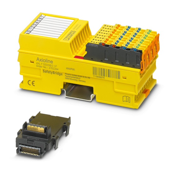
Page 14: Structure Of The Module
Connector for connecting the supply voltage Function identification I/O connector Diagnostics and status indicators DIP switch More detailed information on setting the switches: see Section 4.1.3 “Setting the DIP switch” on page 28. Housing dimensions 53.6 Figure 2-2 Housing dimensions (in mm) PHOENIX CONTACT 105739_en_04... -
Page 15: Safe Digital Outputs
These test pulses are visible at the output and can trigger undesirable reactions with quick responding actuators. The test pulses are either light pulses (brief activation) which can be disabled or dark pulses (brief deactivation) which cannot be disabled. 105739_en_04 PHOENIX CONTACT... -
Page 16: Connection Options For Actuators Depending On The Parameterization
SIL 3/SILCL 3/Cat. 4/PL e For connection example, see page * If the test pulses are disabled, a cross-circuit between the outputs is only detected if the output is enabled. To achieve Cat. 3, two-channel actuators are usually used. PHOENIX CONTACT 105739_en_04... -
Page 17: Local Diagnostics And Status Indicators
(Only applies if UO is on or flashing at the same time.) Red on Hardware fault. Communication to the higher-level controller is disabled. The module has entered the safe state (failure state). Flashing red The module is not parameterized. 105739_en_04 PHOENIX CONTACT... - Page 18 Status of each output from 0 - 7 Output at logic “0”. Green on Output at logic “1”. 10 - 17 Diagnostics for each output from 0 - 7 No error present at the output. Red on Error at the output (e.g., short circuit). PHOENIX CONTACT 105739_en_04...
-
Page 19: Safe State
51. Information on which errors are detected and when: see Section 6 “Connection examples for safe outputs” on page 37. If an error occurs on a channel of an output parameterized as “two-channel”, the other corresponding channel also enters the safe state. 105739_en_04 PHOENIX CONTACT... -
Page 20: Device Errors
Sequential errors can result in the loss of the safety function. • In the event of a device error, the module should be completely disconnected from the power supply and replaced so as to prevent sequential errors. PHOENIX CONTACT 105739_en_04... -
Page 21: Parameterization Errors
(e.g., by changing the order of PROFIsafe containers with the same consecutive number). Programming data/configuration data Phoenix Contact provides device description files for various control systems. The programming data/configuration data is defined in the device description (FDCML, GSD, GSDML, etc.) according to the bus or network used. - Page 22 AXL F PSDO8/3 1F PHOENIX CONTACT 105739_en_04...
-
Page 23: Integration Of The Axioline F Local Bus
Integration of the Axioline F local bus The module is integrated for operation in an Axioline F station. More detailed information on the structure of an Axioline F station: see UM EN AXL F SYS INST user manual. Supply voltage of the module logic The supply voltage for the module logic is generated in the bus coupler and led to the Axioline F module via the bus base module. -
Page 24: Supply Voltage U
24 V DC external fuse (PELV) 230 V or supply at the Axioline F module 24 V GND for supply at a bus coupler or a power terminal 105739B000_en Figure 3-1... -
Page 25: Dc Distribution Network According To Iec 61326-3-1
Terminal point assignment Figure 3-2 Terminal point assignment The Axioline F connectors are supplied with the module. They are color coded and marked for connection. Only use the connectors supplied with the module. The following applies for the tables below: –... - Page 26 Parasitic voltages can result in the loss of the safety function. • Connect the actuator ground to the ground terminal point of the corresponding output on the Axioline F connector. An external ground may not be used. PHOENIX CONTACT 105739_en_04...
-
Page 27: Assembly, Removal, And Electrical Installation
• Before assembling or removing the module, disconnect the power to the module and the entire Axioline F station and make sure that the system cannot be switched on again. •... -
Page 28: Setting The Dip Switch
Remove the marking field and set the address in the switch below it. • Reattach the marking field to the module. The set address is only applied on power up. If the address is adjusted during operation, the module responds with a failure state. PHOENIX CONTACT 105739_en_04... -
Page 29: Mounting And Removing The Module
Insert a suitable tool (e.g., bladed screwdriver) into the upper and lower snap- on mechanisms (base latches) of the module one after the other to release it (A). • Remove the module perpendicular to the DIN rail (B). 105739_en_04 PHOENIX CONTACT... - Page 30 • Press firmly on the connector. Make sure that the locking latch snaps in. Remove • Release the locking latch (A). • Tilt the connector upwards slightly (B). • Remove the connector from the module (C). PHOENIX CONTACT 105739_en_04...
-
Page 31: Electrical Installation
– Connecting the supply voltages for the Axioline F station • Carry out electrical installation for the Axioline F station according to the following user manuals: – Axioline F: system and installation user manual, UM EN AXL F SYS INST –... - Page 32 AXL F PSDO8/3 1F PHOENIX CONTACT 105739_en_04...
-
Page 33: Parameterization Of The Module
Information on error messages and troubleshooting: see Section 8 “Errors: messages and removal” on page 51. F-Parameters and Assign the parameterizable F-Parameters and i-Parameters. Overview of the module i-Parameters parameters and possible settings: Section “Appendix: F-Parameters and i-Parameters” on page 73. 105739_en_04 PHOENIX CONTACT... -
Page 34: Parameterization Of The Safe Outputs
However, outputs parameterized as “Not used” are tested with test pulses. Observe the additional information: see “Requirements for actuators/controlled devices” on page 15, see Section 6 “Connection examples for safe outputs” on page 37. PHOENIX CONTACT 105739_en_04... -
Page 35: Behavior Of The Outputs In The Event Of Enabled Switch-Off Delay For Stop Category 1
If the parameterization is modified before switch-off is complete, a diagnostic message is generated. – If the parameterization is modified, this can result in delayed startup due to the switch-off delay. • Carry out a validation every time the parameterization is modified. 105739_en_04 PHOENIX CONTACT... - Page 36 AXL F PSDO8/3 1F PHOENIX CONTACT 105739_en_04...
-
Page 37: Connection Examples For Safe Outputs
The examples only describe the options for the electrical connection of controlled devices/actuators to the safe outputs. Should you have any questions regarding your applications, please contact the Phoenix Contact safety hotline: see Section 1.8 “Safety hotline” on page 12. 105739_en_04 PHOENIX CONTACT... -
Page 38: Notes On The Protective Circuit Of External Relays/Contactors (Freewheeling Circuit)
• Please note that the freewheeling circuit affects the fall time and the service life of the contactor. • Please observe the specifications of the relay manufacturer when dimensioning the relay protective circuit. PHOENIX CONTACT 105739_en_04... -
Page 39: Measures To Achieve A Specific Safety Integrity
Please note that all errors that cannot be detected can result in the loss of the safety function. Take measures to prevent these errors (e.g., protected cable installation or double insulation). Observe the notes in the following tables. Please take into consideration errors with a common cause. 105739_en_04 PHOENIX CONTACT... -
Page 40: Single-Channel Assignment Of Safe Outputs
Parasitic voltages can result in the loss of the safety function. • Connect the actuator ground to the ground terminal point of the corresponding output on the Axioline F connector. An external ground may not be used. PHOENIX CONTACT 105739_en_04... - Page 41 WARNING: Unexpected machine startup An operator acknowledgment can result in unexpected machine startup. • Please note that an operator acknowledgment can result in the outputs being re-enabled. SF = safety function OUTx = diagnostic message (LED) for each output X 105739_en_04 PHOENIX CONTACT...
- Page 42 AXL F PSDO8/3 1F Typical parameterization Parameterization Parameterized as Comment Assignment Used Test pulses (output disabled) Enabled Or disabled (in software: test impulses (output switched off)) Switch-off delay for stop Enabled Or disabled category 1 Output Single-channel PHOENIX CONTACT 105739_en_04...
-
Page 43: Two-Channel Assignment Of Safe Outputs
• Connect the actuator ground to the ground terminal point of the corresponding output on the Axioline F connector. An external ground may not be used. The failure detection time does not have to be taken into consideration for two-channel assignment. - Page 44 WARNING: Unexpected machine startup An operator acknowledgment can result in unexpected machine startup. • Please note that an operator acknowledgment can result in the outputs being re-enabled. SF = safety function OUTx = diagnostic message (LED) for each output X PHOENIX CONTACT 105739_en_04...
- Page 45 Parameterization Parameterized as Comment Channel 1 Channel 2 Assignment Used Used Test pulses (output disabled) Enabled Enabled (in software: test impulses (output switched off)) Switch-off delay for stop Enabled Enabled Or disabled category 1 Output Two-channel Two-channel 105739_en_04 PHOENIX CONTACT...
- Page 46 AXL F PSDO8/3 1F PHOENIX CONTACT 105739_en_04...
-
Page 47: Startup And Validation
– Make sure that functional earth ground is connected. Connect the necessary voltages to the Axioline F station. UM EN AXL SYS INST user manual or documentation for the module Connect the necessary voltages (U ) to the module. -
Page 48: Startup Mode
The red CM LED indicates that the device is in startup mode. In the Startup+ software, enter the address set on the device. For additional information on the Startup+ software, refer to the documentation for the software. The software can be downloaded free of charge at phoenixcontact.net/products. PHOENIX CONTACT 105739_en_04... -
Page 49: Restart After Replacing A Module
• Before assembling or removing the module, disconnect the power to the module and the entire Axioline F station and make sure that the system cannot be switched on again. •... - Page 50 AXL F PSDO8/3 1F PHOENIX CONTACT 105739_en_04...
-
Page 51: Errors: Messages And Removal
Reading diagnostic messages Diagnostic messages are read via communication objects. For additional information on communication objects and general Axioline F error messages, please refer to the following user manuals: Documentation –... - Page 52 Value without sign bit, only positive values from 00 ... FF Unsigned 16 Value without sign bit, only positive values from 0000 ... FFFF Unsigned 32 Value without sign bit, only positive values from 0000 0000 ... FFFF FFFF PHOENIX CONTACT 105739_en_04...
-
Page 53: Diagstate Object 0X0018
DiagStateChannelNo object Index Object Object Data Rights Meaning name type type [bytes] 0x0033 DiagState- Record Diagnostic state ChannelNo Consecutive Unsigned 16 Consecutive error number since the last reset or error memory reset ChannelNo Unsigned 8 Affected channel 105739_en_04 PHOENIX CONTACT... -
Page 54: Diagstateaddvalue Object 0X0034
The next error is then output. Table 8-8 ResetDiag object Index Object Object Data Rights Meaning name type type [bytes] 0x0019 ResetDiag Unsigned 8 Reset diagnostics; deletes the corresponding diagnostic memory and acknowledges the message PHOENIX CONTACT 105739_en_04... -
Page 55: Examples For Reading A Diagnostic Message
Text: Read DiagStateChannelNo object 0x0033 Consecutive no.: 2 ChannelNo: 0x0000 Read DiagStateAddValue object 0x0034 Consecutive no.: 2 AddValue: 0x0230 This error cannot be acknowledged as it is a priority 1 error. • Check and correct the parameterization. 105739_en_04 PHOENIX CONTACT... -
Page 56: Error Codes
AXL F PSDO8/3 1F Error codes Please contact Phoenix Contact if error codes are indicated by the system which do not appear in: – The tables below in this user manual – The Axioline F: system and installation user manual, UM EN AXL F SYS INST –... -
Page 57: Safe Digital Output Errors
(brief deactivation). As a result all This diagnostic message can be outputs are kept in the safe state. OUT: acknowledged. Acknowledgment deletes the message and enables the outputs. The error may need to be acknowledged several times. 105739_en_04 PHOENIX CONTACT... -
Page 58: Supply Voltage Errors
This diagnostic message can be All module outputs are kept in the acknowledged. Acknowledgment safe state. deletes the message and enables The U LED is permanently on again the outputs. as soon as no undervoltage can be detected. PHOENIX CONTACT 105739_en_04... -
Page 59: Parameterization Errors
0x6320 Device type ID is Check whether the correct module is incorrect or wrong being used. + 0x03FB module is being used If you are unable to remove the error, please contact Phoenix Contact. 105739_en_04 PHOENIX CONTACT... -
Page 60: General Errors
DIP switch moved during FS on The module switches to the safe Check DIP switch position. operation state. Perform power up. This diagnostic message cannot be acknowledged. PHOENIX CONTACT 105739_en_04... -
Page 61: Profisafe Errors
– A safety-related input is automatically reset to “1” when the safety function trigger is reset. • If you do not want the machine to restart automatically, configure the safety logic accordingly. 105739_en_04 PHOENIX CONTACT... - Page 62 AXL F PSDO8/3 1F PHOENIX CONTACT 105739_en_04...
-
Page 63: Maintenance, Repair, Decommissioning, And Disposal
In this case, the correct operation of the safety module can no longer be ensured. • In the event of an error, send the module to Phoenix Contact or contact Phoenix Contact immediately and engage a service engineer. Decommissioning and disposal Carry out decommissioning according to the requirements of the machine or system manufacturer. - Page 64 AXL F PSDO8/3 1F PHOENIX CONTACT 105739_en_04...
-
Page 65: 10 Technical Data And Ordering Data
III (PELV), IEC 61140, EN 61140, VDE 0140-1 Gases that may endanger functions according to DIN 40046-36, Not resistant to gas that may endanger functions (sulfur dioxide (SO DIN 40046-37 hydrogen sulfide (H Resistance of the housing material to fungal decay Resistant 105739_en_04 PHOENIX CONTACT... - Page 66 AXL F PSDO8/3 1F General data [...] Ambient compatibility Not resistant to organic chlorine compounds Connection data for Axioline F connectors Connection method Spring-cage terminal blocks Conductor cross section Solid: 0.5 mm to 1.5 mm Flexible without sleeve: 0.25 mm to 1.5 mm...
- Page 67 Only use PELV power supply units with at least four times the nominal tripping current, as this is the only way to ensure tripping times of less than 300 ms. Undervoltage detection Yes, at approximately 17 V Diagnostics indicators Green U LED: see Section 2.6 “Local diagnostics and status indicators” on page 17 External protection 8 A slow-blow, maximum 105739_en_04 PHOENIX CONTACT...
- Page 68 The switch-on pulse can result in the loss of the safety function. • Please note that the load on a switch-on pulse (light test) of 1 ms must not fail or respond in a safety-critical way. • Please take this into consideration when selecting the actuator. PHOENIX CONTACT 105739_en_04...
-
Page 69: Conformance With Emc Directive
WARNING: Loss of safety function Parasitic voltages can result in the loss of the safety function. • Connect the actuator ground to the ground terminal point of the corresponding output on the Axioline F connector. An external ground may not be used. •... -
Page 70: Ordering Data And Download Data
Ordering data: module Description Type Order No. Pcs./Pkt. Axioline F module with safe digital outputs AXL F PSDO8/3 1F 2701560 10.4.2 Download data: documentation Make sure you always use the latest documentation. It can be found in the download area for the specified product at phoenixcontact.net/products. -
Page 71: A Appendix: Glossary For Profisafe
F-Device. F_Par_CRC A CRC signature which is created via all F-Parameters and ensures error-free transmission of the F-Parameters. F-Slave Failsafe slave F-Source_Address F-Parameter, PROFIsafe source address; address of the safe controller: see also “F-Parameter” 105739_en_04 PHOENIX CONTACT... - Page 72 (F-I/O device) via DIP switches and then configured in the configuration tool for the safe controller used. PROFIsafe monitoring Monitoring time for safety-related communication between the safe controller (F-CPU) and time safe I/O device (F-I/O device). This time is parameterized in the F_WD_Time F-Parameter. PHOENIX CONTACT 105739_en_04...
-
Page 73: B Appendix: F-Parameters And I-Parameters
The value must be greater than 0. When verifying the safety function, check whether the F_iPar_CRC parameter is greater than 0 for all devices. If not, check the i-Parameters and the CRC checksum in the i-Parameter and F-Parameter. 105739_en_04 PHOENIX CONTACT... -
Page 74: B 2 I-Parameters
The i-Parameters are individual module parameters. These include: – Module parameters: see Section 5.2 “Parameterization of the safe outputs” on page 34 – PST_Device_ID (device type ID) iPar_CRC The module parameters are verified with a checksum: iPar_CRC. PHOENIX CONTACT 105739_en_04... -
Page 75: B 3 Diagnostic Messages For Parameter Errors For Profisafe
CRC1 transmitted in the parameter telegram. Device-specific diagnostics. Save i-Parameter watchdog time exceeded. Restore i-Parameter watchdog time exceeded. Invalid F_iParCRC. Correct value. F_Block_ID is not supported. Check device description. Reserved. Reserved. Non-specified (unknown) error. 105739_en_04 PHOENIX CONTACT... - Page 76 AXL F PSDO8/3 1F Table B-3 i-Parameter parameter errors AddValue Error cause Remedy (hex) 03F2 iPar_CRC is incorrect. Check i-Parameters. Repeat calculation. 03FB PST_Device_ID is incorrect. Contact Phoenix Contact. PHOENIX CONTACT 105739_en_04...
-
Page 77: C Appendix: Index
Operating time ............. 19 Ordering data............... 65 Outputs ................ 15 Error code ..............56 Device errors............20 Error location............51, 56 I/O errors ..............19 Errors Parameterization ............ 34 General ..............60 Positive switching........... 15 Hardware..............60 Requirements for actuators ........15 105739_en_04 PHOENIX CONTACT... - Page 78 PROFIsafe address............33 Unsigned 16..............52 Protective circuit............38 Unsigned 32..............52 Unsigned 8..............52 Use, intended............... 11 Qualified personnel ............9 Validation ..............49 Record .................52 Var ................52 Removal...............29 Visible string..............52 Repair ................63 Replacement, module ..........49 Restart .................49 PHOENIX CONTACT 105739_en_04...
-
Page 79: D Appendix: Checklists
These requirements must be met for a safety application, in order to complete the relevant phase using the checklist. Requirement (optional) These requirements are optional. For points that are not met, please enter an appropriate comment in the relevant field. 105739_en_04 PHOENIX CONTACT... -
Page 80: D 1 Planning
16 Have specifications for assembly and electrical installation been defined (e.g., EPLAN) and communicated to the relevant personnel? 17 Have specifications for startup been defined and communicated to the relevant personnel? Date Signature (editor) Date Signature (test engineer) PHOENIX CONTACT 105739_en_04... -
Page 81: D 2 Assembly And Electrical Installation
No. Requirement (optional) No Comment Is the data width set correctly according to the specifications? Is the profile/PROFIsafe address set correctly according to the specifications? Date Signature (editor) Date Signature (test engineer) 105739_en_04 PHOENIX CONTACT... -
Page 82: D 3 Startup And Parameterization
No. Requirement (optional) No Comment Have safety distances that must be observed been calculated according to the response and delay times implemented? Date Signature (editor) Date Signature (test engineer) PHOENIX CONTACT 105739_en_04... -
Page 83: D 4 Validation
PELV? 10 Has the power supply of U and U in the Axioline F system from a power supply unit been implemented? 11 Is external protection of the module implemented (according to the specifications in this user manual for supply voltage U... - Page 84 AXL F PSDO8/3 1F PHOENIX CONTACT 105739_en_04...
-
Page 85: E Appendix: Revision History
17 Note on “Operating time in the error state” revised page 19 Section 3, “Integration of the Axioline F local bus” / Section 3.1, “Supply voltage of the page 23 module logic” revised Figure 4-1 “DIP switch” and “Overview of the switch positions” revised page 28 Section 7.1.1, “Startup mode”... - Page 86 AXL F PSDO8/3 1F PHOENIX CONTACT 105739_en_04...
Need help?
Do you have a question about the Axioline F and is the answer not in the manual?
Questions and answers