Table of Contents
Advertisement
Quick Links
Advertisement
Table of Contents

Subscribe to Our Youtube Channel
Summary of Contents for DeVilbiss COBRA 3C
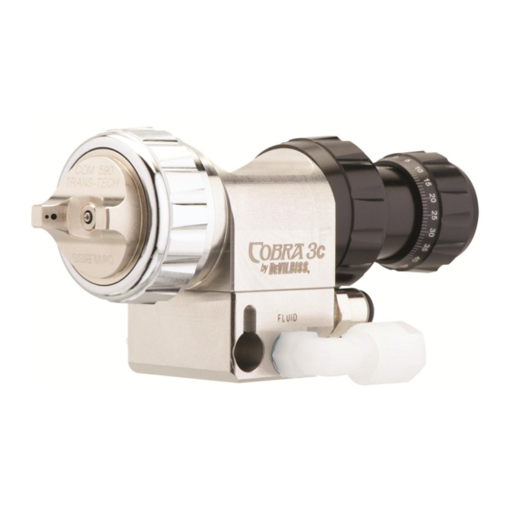
- Page 1 SB-E-2-741 ISS.03 II 2 G X T6 Operation Manual COBRA 3C – Automatic Spray Gun...
-
Page 2: Table Of Contents
Table of Contents Topic Page Characteristics EC Declaration of Conformity Safety Warnings Model Part Numbers Table 1: Air Cap Range Table 1: Fluid Nozzle & Needle Range Specification & Materials of Construction Exploded View Parts List Dimensions Air Connection Maintenance Body Removal Piston/Needle Removal Needle Packing Removal... -
Page 3: Characteristics
We, Finishing Brands UK Limited, Ringwood Rd, Bournemouth, Dorset, BH11 9LH, UK as the manufacturer of the spray gun model Cobra 3C, declare, under our sole responsibility that the equipment to which this document relates is in conformity with the following standards or other normative documents: BS EN 12100:2010, BS EN 1953:2013;... -
Page 4: Safety Warnings
Safety Warnings Fire and explosion Solvents and coating materials can be highly flammable or combustible when sprayed. ALWAYS refer to the coating material supplier’s instructions and COSHH sheets before using this equipment. Users must comply with all local and national codes of practice and insurance company requirements governing ventilation, fire precautions, operation and house-keeping of working areas. -
Page 5: Model Part Numbers
Model Part Numbers CBA3C - ##### - ### N Type of Air Cap Type Hardened (See Table 1) Fluid Nozzle Size (See Table 2) e.g. CBA3C-590-085N e.g. CBA3C-590HV-10N Where:- Where:- 590= 590 Trans-Tech Air Cap 590HV= 590HV HVLP Air Cap 085=0.85mm Fluid Nozzle and Needle 10= 1.0mm Fluid Nozzle and Needle N= Hardened Fluid Nozzle and Needle... -
Page 6: Exploded View
© 2014 Finishing Brands UK Ltd. -
Page 7: Parts List
PARTS LIST REF. DESCRIPTION PART NO. QTY. AIR CAP ASSEMBLY SEE TABLE 1, p5 FLUID NOZZLE KIT SEE TABLE 2, p5 FLUID NOZZLE SEPARATOR - KIT OF 5 SP-626-K5 BODY NEEDLE PACKING KIT SPA-408-K NEEDLE PACKING - KIT OF 2 SPA-118-K2 PACKING NUT O-RING... -
Page 8: Dimensions
Dimensions ” BSP A - FLUID INLET (x2) ” BSP B- TRIGGER / CYLINDER AIR INLET ” BSP C- LENGTH AIR INLET ” BSP D- PATTERN AIR INLET E- M6 MOUNTING HOLES (x2) F- M4 BODY / MANIFOLD CONNECTION HOLE ©... -
Page 9: Air Connection
Air Connection Fan air supply Atom air supply Pressure regulator Pressure regulator 0-1 Bar / 0-15 psi recommended 0-1 Bar / 0-15 psi recommended 12 Bar / 174 psi maximum 12 Bar / 174 psi maximum Trigger / Cylinder Air 3/2 Valve 3.5-6 Bar / 51-87 psi Important: The spray gun must be earthed to dissipate any electrostatic charges which may be... -
Page 10: Maintenance
MAINTENANCE WARNING – Check all air and fluid pressure is removed before starting maintenance. Body Removal 1.8-2.0 Nm 1.3-1.5 lbf.ft © 2014 Finishing Brands UK Ltd. -
Page 11: Piston/Needle Removal
Piston/Needle Removal Note: O-Ring assembled into 2 undercut. Needle Packing Removal Tighten Packing nut to torque of 5 Nm (44 Ibf/in) when re-assembling. © 2014 Finishing Brands UK Ltd. -
Page 12: Fluid Nozzle Removal
Fluid Nozzle Removal 10mm Tighten nozzle to torque of 15 Nm (133 Ibf/in) when re-assembling. Manifold O-Ring and Connector Removal/Assembly © 2014 Finishing Brands UK Ltd. -
Page 13: Setting Micrometer
Setting Micrometer Zero (0mm Needle stroke) Screw in knob until it touches stop. 1.5mm Note: Do not over tighten. Rotate barrel using key as a lever until the horizontal scale is in line with “0” on the knob. Re-tighten screw. Indexing Air Cap 90°... -
Page 14: Troubleshooting
Troubleshooting Possible Problems in Operation CONDITION CAUSE CORRECTION Spray Pattern Heavy top or bottom pattern. Horn holes plugged. Clean with non-metallic point. Obstruction on top or bottom of fluid Clean. nozzle. Cap and/or nozzle seat dirty. Clean. Left or right side horn holes plugged. Clean with non-metallic point. - Page 15 Possible Problems in Operation (cont.) Increase Fluid Flow. Inadequate material flow. Fluid Starved spray Change to larger fluid nozzle size. pattern. Check hose for blockage. Air pressure too high. Reduce air pressure. Excessive overspray. Gun too far from work surface. Adjust to correct target distance.
-
Page 16: Accessories
ACCESSORIES Fluid Needle Mounting Bar SPA-406-K SPA-407-K Removal Tool 1.5mm Allen 2mm Allen SPN-10-K SPN-11-K T20 Torx Key SPN-8-K2 Indexing Ring SPA-112 4mm Allen 10mm Spanner WARRANTY This product is covered by Finishing Brands UK Limited one year warranty. Finishing Brands UK Limited, Ringwood Road, Bournemouth, BH11 9LH,...


Need help?
Do you have a question about the COBRA 3C and is the answer not in the manual?
Questions and answers