Table of Contents
Advertisement
SERVICE MANUAL
EN
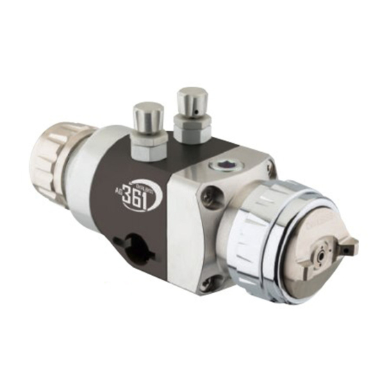
DEVILBISS AG360
Series:
AG361 & AG361E
Low Pressure, Air Atomisation Automatic Spray
Guns.
II 2 G X T6
IMPORTANT! DO NOT DESTROY
It is the Customer's responsibility to have all operators and service personnel read and understand
this manual.
Contact your local DeVilbiss representative for additional copies of this manual.
READ ALL INSTRUCTIONS BEFORE OPERATING THIS DEVILBISS PRODUCT.
1/24
SB-E-2-642 R3.1
Advertisement
Table of Contents

Related Manuals for DeVilbiss AG361


Summary of Contents for DeVilbiss AG361
- Page 1 IMPORTANT! DO NOT DESTROY It is the Customer's responsibility to have all operators and service personnel read and understand this manual. Contact your local DeVilbiss representative for additional copies of this manual. READ ALL INSTRUCTIONS BEFORE OPERATING THIS DEVILBISS PRODUCT. 1/24...
-
Page 2: Functional Description
FUNCTIONAL DESCRIPTION The AG361 and AG361E low pressure air atomising spray guns are designed to be cost effective guns with maximum control and serviceability. The AG361 is intended for most types of general industrial coating and fine finishing operations, suitable for both waterbased and solventbased applications. -
Page 3: Protection Level
Product Description / Object of Declaration: AG361, AG361E This Product is designed for use with: Solvent and water based materials Suitable for use in hazardous area: Zone 1 / Zone 2 Protection Level: II 2 G X T6 Notified body details and role:... - Page 4 In this part sheet, the words WARNING, CAUTION and NOTE are used to emphasise important safety information as follows: WARNING CAUTION NOTE Hazards or unsafe practices which could result in Hazards or unsafe practices which could result in Important installation, operation or maintenance severe personal injury, death or substantial minor personal injury, product or property information.
- Page 5 AG361 GUN PART NUMBER FORMAT & PART SELECTION GUIDE AIR CAP FLUID TIP Conventional Size & construction See table 2 Trans-Tech/Compliant HVLP See table 1 AG361 TE40 BACK END OPTIONS VALVE OPTIONS Ratchet Control Valve Fixed Plugged Micrometer Remote TABLE 1...
- Page 6 TABLE 2 AG361 RECOMMENDED FLUID TIP / AIR CAP COMBINATIONS Air Cap Atomisation Type 0.5mm 0.7mm 0.85mm 1.0mm 1.2mm 1.4mm 1.6mm 1.8mm 2.0mm 2.2mm 2.8mm Conventional Conventional Conventional For Conventional tip & needle part numbers, see table 3. TE10 Trans-Tech...
- Page 7 AG361E CERAMIC & ENAMEL INDUSTRY GUN PART NUMBER FORMAT & PART SELECTION GUIDE AIR CAP FLUID TIP Conventional Size & construction See table 5 See table 6 AG361E BACK END OPTIONS VALVE OPTIONS Ratchet Control Valve Fixed Plugged Remote TABLE 5 - AG361E AIR CAP PERFORMANCE GUIDE Recommended Typical Fluid Typical Fan Pattern...
- Page 8 TYPICAL AIR CONNECTION SCHEMATIC Compressed air take-off Shut-off valve Air filter Air regulator & gauge 3/2 solenoid valve, normally closed Quick exhaust valve & silencer CAP - 1/4" G CYL - 1/8" G WARNING The spray gun must be earthed to dissipate any electrostatic charges which may be created by fluid or air flows.
- Page 9 TYPICAL FLUID CONNECTION SCHEMATIC Fluid filter Fluid supply Fluid restrictor valve Fluid reservoir Fluid - 1/4" G NOTE Protective coatings have been used for storage protection. Flush the equipment fluid passageways with appropriate solvent before use. 9/24 SB-E-2-642 R3.1...
-
Page 11: Parts List
SPA-420-K CERAMIC PACKING ASSY (AG361E ONLY) SPA-157-K PACKING SPACER SPA-29X-K4 O RING (KIT OF 4) SPA-180X-K2 O RING (KIT OF 2) SPA-151-K AG361 BODY S-14193 HEXAGON SOCKET SET SCREW SPA-414-K CONTROL VALVE SPA-6X-K PISTON & SEAL KIT S-28220X-K2 O RING (KIT OF 2) -
Page 12: Typical Setting
TYPICAL SETTING The ATOM air valve controls the length of the fan pattern, the FAN valve controls the shape of the pattern. To increase the air pressure, turn air control valves anti-clockwise and to reduce the pressure turn clockwise. Fluid flow can be adjusted with the needle adjustment knob, fluid flow is increased when you turn the knob anti-clockwise. -
Page 13: Maintenance
MAINTENANCE KEY - MAINTENANCE SYMBOLS Order for disassembly (reverse for assembly) Item Number Petroleum Grease/Jelly Thread Sealant Thread Locker DISASSEMBLY TIP & NEEDLE 13/24 SB-E-2-642 R3.1... - Page 14 DISASSEMBLY PACKING DISASSEMBLY PISTON 14/24 SB-E-2-642 R3.1...
- Page 15 TROUBLESHOOTING MECHANICAL PERFORMANCE GENERAL FAULTS CAUSE CORRECTION No air pressure at gun. Check air supply and air line. Will not spray. Fluid needle adjustment knob not Open fluid needle adjustment knob. open enough. Check fluid tip/needle selection Incorrect needle fitted to gun. chart and fit correct item.
- Page 16 FLUID FAULTS CAUSE CORRECTION Fluid tip internal seat scored Replace. damaged or worn. Fluid needle external profile Replace. damaged or worn. Contamination on needle or tip mating surfaces preventing good Thoroughly clean. Slow fluid leak from fluid tip and seal. needle seat.
- Page 17 TROUBLESHOOTING SPRAY PERFORMANCE CONDITION CAUSE CORRECTION Heavy top or bottom pattern. Material build-up on air cap, Soak cap or tip in suitable solvent plugged horn holes, centre holes or and thoroughly clean. jets. Material build-up on fluid tip exterior Replace fluid tip or air cap if or partially plugged fluid tip.
- Page 18 Heavy centre pattern. Turn out counter clockwise to Pattern adjustment valve set too low. achieve correct pattern. Reduce fluid flow by turning fluid Too much material. needle adjusting screw clockwise. Reduce fluid pressure. Material too thick. Thin to correct consistency. Atomising air pressure too low.
- Page 19 Ball end heavy pattern. Change fluid tip for smaller size or Too much fluid flow. change air cap for different specification air cap. Too much atomisation air pressure. Reduce air pressure. Excessive bounce-back. Check distance (normally 150- Gun too far from surface. 200mm).
- Page 20 DIMENSIONS 20/24 SB-E-2-642 R3.1...
- Page 21 ACCESSORIES DESCRIPTION PART No. SPA-417-K Micrometer needle adjustment assembly. SPA-167-K Fixed needle position end cap. SPA-426-K Ratchet needle adjustment assembly. Remote atomisation & fan air control fittings. Replaces items (17) SPA-22-K2 see exploded view. Atomisation & fan blanking plugs, replaces items (17) see exploded SPA-111-K2 view.
- Page 22 NOTES 22/24 SB-E-2-642 R3.1...
- Page 23 NOTES 23/24 SB-E-2-642 R3.1...
-
Page 24: Warranty Policy
DeVilbiss®, Ransburg®, MS®, BGK®, and Binks® are registered trademarks of Carlisle Fluid Technologies, Inc.,dba Finishing Brands. © 2016 Carlisle Fluid Technologies,Inc., dba Finishing Brands. All rights reserved. DeVilbiss is part of Finishing Brands, a global leader in innovative spray finishing technologies. USA/Canada www.devilbiss.com info@carlisleft.com...
Need help?
Do you have a question about the AG361 and is the answer not in the manual?
Questions and answers