Table of Contents
Advertisement
Advertisement
Table of Contents

Related Manuals for DeVilbiss GTI PRO LITE


Summary of Contents for DeVilbiss GTI PRO LITE
- Page 1 GTI PRO LITE HVLP & LVMP Operation Manual...
-
Page 2: Table Of Contents
Table of Contents EC DECLARATION OF CONFORMITY ........................3 PART NUMBERS ................................. 3 OPERATIONAL DESCRIPTION ..........................3 KIT CONTENTS (ALL MODELS) ..........................4 CONSTRUCTION FEATURES ............................ 4 MATERIALS OF CONSTRUCTION ..........................4 SPECIFICATIONS & TECHNICAL DATA ........................4 SAFETY WARNINGS ..............................5 PARTS LIST ................................. -
Page 3: Ec Declaration Of Conformity
If there is any doubt regarding the suitability of a specific material, contact your DeVilbiss Distributor or DeVilbiss direct. NOTE: This gun is not to be used with halogenated hydrocarbon solvents or cleaning agents such as 1,1,1,-Trichloroethane or methylene chloride. -
Page 4: Kit Contents (All Models)
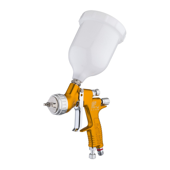
Anodised, forged aluminium gun body (ergonomic, good looking & durable, easy to clean) Fluid Inlet (3/8 BSP thread – accepts DeVilbiss and 500cc Acetal Cup (easy clean, anti-static) most other cup systems) Air Inlet (universal thread, accepts G 1/4 & 1/4 NPS) -
Page 5: Safety Warnings
SAFETY WARNINGS Fire and explosion Solvents and coating materials can be highly flammable or combustible when sprayed. ALWAYS refer to the coating material supplier’s instructions and COSHH sheets before using this equipment. Users must comply with all local and national codes of practice and insurance company requirements governing ventilation, fire precautions, operation and house-keeping of working areas. -
Page 6: Parts List
PARTS LIST REF. REF. DESCRIPTION PART NO. DESCRIPTION PART NO. Air Cap Retaining Ring Air Inlet Colour ID Ring Kit Slip Ring SN-26-K4 (4Colours) Air Cap Air Inlet Kit SN-9-K Air Cap Retaining Clip JGA-156-K5 Needle Packing Retaining Ring Seal Packing Spring See chart 1 Aircap &... -
Page 8: Installation
Adjust inlet air pressure if required. INSTALLATION Turn fluid adjusting knob (28) counter clockwise For maximum transfer efficiency, do not use more 5 turns for full needle travel. pressure than is necessary to atomise the material Test spray. If the finish is too dry, reduce airflow being applied. -
Page 9: Parts Replacement/Maintenance
Parts Replacement/Maintenance AIR VALVE INSTRUCTIONS Servicing Air Valve Reasons to service air valve: A) Air valve not functioning correctly (may need cleaning). B) Routine maintenance. C) Air leaks. 1. Remove trigger screw (38) with Torx tool (55) or Torx T20 key. (See fig 2). 2. - Page 10 8. Withdraw the valve seat (19) from the gun body. (See fig 10). 9. Push out the front airvalve seal (18) with a finger. (See fig 11). 10. Turn the Gun upside down and let the seal fall out. (See fig 12). 11.
-
Page 11: Needle Packing Replacement Instructions
Parts Replacement/Maintenance NEEDLE PACKING REPLACEMENT INSTRUCTIONS 1. Remove trigger and needle following steps 1 to 6 on P9, servicing airvalve. 2. Loosen and remove packing nut using Key (57) or a straight blade screwdriver. (See figs 18 & 19) 3. Discard old packing (34) and packing spring (35) if replacing. -
Page 12: Spray Head Seal Replacement
Parts Replacement/ Maintenance SPRAY HEAD SEAL REPLACEMENT Remove air cap and retaining ring (6). (See fig 26). Remove fluid adjusting knob (28), spring (25), and spring pad (26). (See fig 27). Remove fluid needle (24) from gun body. (See fig 28). -
Page 13: Parts Replacement/Maintenance
Parts Replacement/Maintenance Chart 1 – Air Caps RECOMMENDED AIR FLOW PART No. FOR MARKING ON TECHNOLOGY INLET PRESSURE (L/min) @ 2 AIR CAP AIR CAP (bar) PROLT-GTE10-1314 LVMP TE10 PROLT-GTE20-1314 LVMP TE20 PROLT-GHV30-1314 HVLP HV30 PROLT-GT110-1314 LVMP T110 NOTE: When removing air cap from retaining ring, don’t remove the Slip Ring (2) or Retaining Ring Seal (5) from the Retaining Ring. -
Page 14: Troubleshooting Possible Problems In Operation
Troubleshooting Possible Problems in Operation CONDITION CAUSE CORRECTION Heavy top Horn holes plugged. Clean. Ream with non-metallic point. bottom pattern Obstruction on top or bottom of Clean. fluid nozzle. Clean. Cap and/or nozzle seat dirty. Clean. Ream with non- Left or right side horn holes metallicpoint. - Page 15 Troubleshooting Possible Problems in Operation (cont) Starved spray pattern Inadequate material flow Wind fluid adjusting knob out or change to larger fluid nozzle size Blocked vent in Cup lid Clean lid and unblock vent Low atomisation air pressure Increase air pressure and rebalance gun.
-
Page 16: Accessories
DGIPRO-502- Torx driver SPN-8-K2 Pressure Gauge DIVISION Ransburg Japan KK HP http://www.carlisleft.co.jp ®D VILBISS is a registered trademark of Carlisle Fluid Technologie ®Jupiter is a registered trademark of CFT Ransburg Japan KK. ©2017 Carlisle Fluid Technologies. 2017-07-GTi Pro LITE...
Need help?
Do you have a question about the GTI PRO LITE and is the answer not in the manual?
Questions and answers
Why is my gun leaking from the trigger