Table of Contents
Advertisement
May, 2006
P. O. Box 4149
Winston-Salem, North Carolina 27115-4149
336/661-1556
Fax: 336/661-1660
Champion Manual
www.championindustries.com
Technical Manual
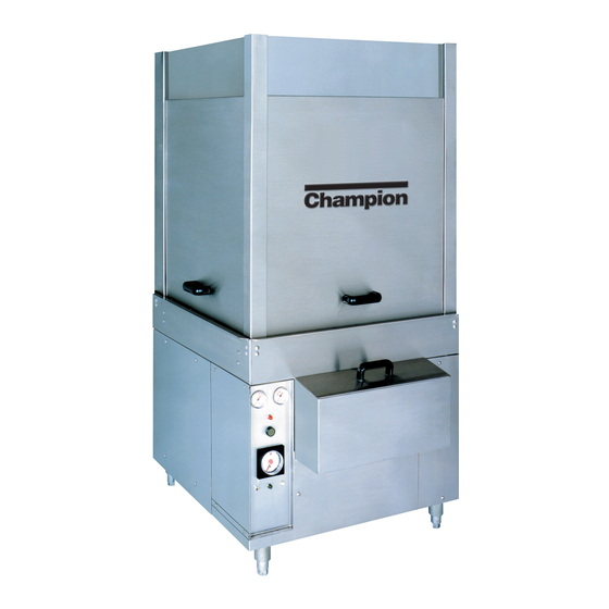
Pot, Pan, and
Utensil Door-type
Models:
PP-28
PP-28 Corner
PP-28 Front Feed
PP-28 Straight Thru
109844
P/N
2674 N. Service Road
Jordan Station, Ontario, Canada L0R 1S0
905/562-4195
Rev C
Fax: 905/562-4618
Advertisement
Table of Contents
Troubleshooting

Related Manuals for Champion PP-28


Summary of Contents for Champion PP-28
- Page 1 Winston-Salem, North Carolina 27115-4149 336/661-1556 Fax: 336/661-1660 Champion Manual www.championindustries.com Technical Manual Pot, Pan, and Utensil Door-type Models: PP-28 PP-28 Corner PP-28 Front Feed PP-28 Straight Thru 109844 2674 N. Service Road Jordan Station, Ontario, Canada L0R 1S0 905/562-4195 Fax: 905/562-4618 Rev C...
- Page 2 Machine Data Plate with Model & Serial number located on left side of control cabinet panel. COPYRIGHT © 2003 by Champion Industries, Inc. Serial Number Phone Phone Champion (Canada) Phone: 1 (905) 562-4195...
-
Page 3: Revision History
REVISION HISTORY Revision Revised Serial Number Date Pages Effectivity 11/01/02 10/13/03 46-47 10/13/03 58-61 J1789 06/21/04 48-49 5/26/06 ----- First issue of manual and replacement parts — Inserted tracks for all models Inserted new piping drawings - moved pressure gauge after solenoid valve. —... -
Page 4: Revision Record
REVISIONS REVISION RECORD (CONT.) -
Page 5: Table Of Contents
REVISION HISTORY ... WARRANTY ... SAFETY SUMMARY ... vi INTRODUCTION ... GENERAL... INSTALLATION ... Unpacking ... Plumbing Connnections ... Electrical Connections ... Ventilation Connections ... Chemical Connections ... Dishtable Connections ... Completing Installation ... OPERATION ... Inital Startup ... Basic Operation ... MAINTENANCE ... - Page 6 TABLE OF CONTENTS Figure 12 — Asco Valve Replacement... 28 Figure 13 — Line Strainer ... 29 Figure 14 — Rear View High Limit ... 30 Figure 15 — Tank Element Placement... 30 Figure 16 — Rear View of Electric Heating Element ... 30 Figure 17 —...
-
Page 7: Limited Warranty
United States and Canada to be free from defects in material and workmanship for a period of one (1) year after the date of installation or fifteen (15) months after the date of shipment by Champion, whichever occurs first. -
Page 8: Safety Summary
• The following general safety rules must be observed in addition to the specific cautions and warnings presented in this manual. • Your Champion pot and pan washer uses hot water to clean and sanitize a variety of wares. Machine surfaces and wares become hot during and immediately following normal operations. -
Page 9: Introduction
All information, illustrations and specifications contained in this manual are based upon the latest product information available at the time of publication. Champion constantly improves its products and reserves the right to make changes at any time or to change specifications or design without notice and without incurring obligation. -
Page 10: General
GENERAL GENERAL This manual covers the Champion pot, pan, and utensil door type washing machine. This machine is fully automatic and is equipped with a 7.5 Hp wash pump motor. This model is available for straight-through, corner or front-loading operation. -
Page 11: Installation
• 1 set of dishracks • Upper and lower spray arm assemblies • Warranty information packet 3. Move the dishwasher to its permanent location. Move the machine while on the skid. Do not lift on any of the piping under the base. INSTALLATION... -
Page 12: Permanent Placement
2. Remove the skid. 3. Place a 3ft. level on top of the pot and pan washer or inside the dishwasher on the track assembly to level the dishwasher front to back. Adjust the level by turning the adjustable feet. -
Page 13: Electrical Connections
Electrical Connections NOTE: Electrical and grounding connections must comply with the National Electrical Code and/or Local Electrical Codes. WARNING: When working on the unit, disconnect the electric service and tag it to indicate work is being done on that circuit. 1. -
Page 14: Chemical Connections
Never use residential nonautomatic dishwashing detergents such as JOY™ or DAWN™, or any other liquid designed for the handwashing of wares, in your machine. Extreme foaming inside your Champion pot and pan washer will cause operation problems. Rinse Aid Connections 1. -
Page 15: Dishtable Connections
3/4” turned down lip. (33-1/2” max entry). 2. The formed down lip of the dishtable should be placed inside the machine. The dishtable should be pitched toward the dishwasher for proper draining by adjusting its leveling feet. The dishtable should be sealed to the dishwasher. -
Page 16: Operation
OPERATION INITIAL START-UP Check your site to ensure that all plumbing and electrical connections have been properly made by qualified personnel. Check the installation of chemical dispensing systems. Perform the following steps to prepare your machine for operation. 1. Check the exterior of the machine for any foreign material and remove. 2. -
Page 17: Basic Operation
BASIC OPERATION Perform the following steps to prepare and load your wares for washing. 1. Scrap and rinse wares to remove any heavy food particles and other debris. 2. Place wares into rack. 3. Place rack into the machine and close all doors. 4. -
Page 18: Maintenance
MAINTENANCE MAINTENANCE The efficiency and life of your machine is increased by regularly scheduled preventive maintenance. A well maintained machine gives better results and service. An investment of a few minutes of daily maintenance will be worthwhile. The best maintenance you can provide is to keep your machine clean. Components that are not regularly cleaned and flushed will clog and become inoperative. -
Page 19: Maintenance Schedule
PREVENTATIVE MAINTENANCE SCHEDULES Daily Maintenance Requirements 1. Check the chemical supply containers and replenish as needed. 2. Inspect the scrap screens and baskets for bent or damaged parts. 3. Check the spray arm bearings and make sure that arms turn freely. 4. -
Page 20: Deliming
6. Open door and add deliming solution (per chemical supplier’s instructions) directly in wash tank. • PP-28 holds 24 US gallons (90.8 Liters) of water. 7. Close doors. 8. Push start button and run an automatic cycle. -
Page 21: Operator Troubleshooting
OPERATOR TROUBLESHOOTING The first step in troubleshooting your dishwasher is knowing how it works under normal conditions. Review the Operation section in this manual for a description of proper loading, operator controls and basic operating procedures. Check the general condition of dishwasher: •... -
Page 22: Troubleshooting Guide
TROUBLESHOOTING OPERATOR TROUBLESHOOTING (CONT.) Troubleshooting Guide In order to find the cause of a breakdown or abnormal operating condition in your dishwasher please ensure that: 1. All switches are ON 2. Drain and overflow tube are in place and seated 3. - Page 23 CONDITION CAUSE Insufficient pumped spray Clogged pump intake screen... Clean pressure Clogged spray pipe ... Clean Scrap screen full ... Must be kept clean and in place Low water level in tank... Check drain and overflow tube Pump motor rotation incorrect ... Reverse connection between L1 Defective pump seal ...
-
Page 24: Basic Service
Use extreme caution when testing circuits while power is applied to the machine. Fill/Rinse Solenoid Valves There are two different types of valves used on the PP-28; Hot Water and Steam valves, both of which are rated 120VAC. The steam booster and steam fill valves come with a four screw pattern on the body. -
Page 25: Hi-Limit Switch
COMPONENTS BASIC SERVICE (CONT.) Hi-Limit Switch On machines with electric tank and boosters, a separate thermostat is installed that interrupts the power if the temperature exceeds a preset limit. When the over temperature condition is resolved, the red button located on top of the switch, must be pushed to reset the power to the elements. Pressure Reducing Valve (PRV) A 3/4”... -
Page 26: Figure 3 — Motor Overload
To Reset the Motor Overload: • Flip the starter switch to the On position. • Run the dishwasher and test the AMP draw of the motor in question. If the motor checks okay then there may be a wiring problem or the overload may be defective. -
Page 27: Figure 4 Wash Pump Timer
ELECTRICAL SERVICE (CONT.) Pump Timer Refer to Fig.4 and Fig. 5 There are two timers in control cabinet of the PP-28, one is located on the face of the cabinet panel and controls the pump time, while the other one is located inside the top of the control cabinet and controls the final rinse time. -
Page 28: Figure 6 Dual Float Switch
ELECTRICAL SERVICE ELECTRICAL SERVICE (Cont.) Automatic Fill/Low Water Heat Protection Dual Float Switches – Refer to Fig. 6 Each tank contains a dual float. The device consists of an angled stem containing two reed switches. Two stainless steel ball floats slide over the stem and are free to move up and down. -
Page 29: Figure7 Tank Heat Thermostats
ELECTRICAL SERVICE (Cont.) Thermostat Locations and Adjustments Refer to Fig. 7 Electric tank heat is controlled by two thermostats. 1. The control thermostat which regulates the temperature. 2. The high limit thermostat which protects from overheating. Location: Both thermostats are located on front of tank, inside a black enclosure box behind the front access panel. - Page 30 ELECTRICAL SERVICE ELECTRICAL SERVICE (Cont.) Heater Element Wiring – Booster Tank and Wash Tank Heater Elements Refer to the illustrations and follow the steps below to properly install terminal jumpers and to make line power connections to a replacement element. Step 1.
- Page 31 6. Motor rotation can be reversed by switching L1 and L2 on 3 phase motors. Single phase motor rotation cannot be reversed 7. Replacement motors are available as complete assemblies. 8. Champion cannot provide replacement bearings, stators, or rotors for motor repair parts. 208-230VAC High Voltage...
- Page 32 ELECTRICAL SERVICE Dual Float Switches – Troubleshooting: The dual float controls fill and heat circuits. Identifying a Dual Float Problem: The most common trouble conditions associated with a dual float failure are: 1. The tank fills constantly. 2. The tank heat will not come on. Inspect the Dual Float: 1.
-
Page 33: Component Replacement
COMPONENT REPLACEMENT Pressure Reducing Valve (PRV) Adjustment 1. Turn the main water supply to machine off. 2. Flip the power toggle switch to OFF. 3. Turn off main incoming power. 4. Loosen the locknut on the adjusting screw in the top of the PRV . 5. - Page 34 COMPONENT REPLACEMENT COMPONENT REPLACEMENT (CONT.) Parker Solenoid Valves These valves have a plunger and diaphragm in seperate enclosures. The diaphragm is between the body and the bonnet. Be careful not to damage the machined faces while the valve is apart. The electrical data for the valve will be found on the coil housing.
- Page 35 COMPONENT REPLACEMENT (CONT.) Asco Solenoid Valves All solenoid operators and valves should be cleaned periodically. The time between the cleanings will vary on the water conditions and the amount of usage. In general, if the voltage to solednoid is correct, sluggish valve operations, excessive noise or leakage will indicate that cleaning is required.
-
Page 36: Figure
COMPONENT REPLACEMENT COMPONENT REPLACEMENT (CONT.) Disassembly/Reassembly of Asco Valve (cont.) 12. Position lip seal, flanged end outward, onto piston assembly. Install piston assembly with lip seal into support in valve body cavity. 13. Replace piston spring, valve bonnet, and bonnet screws. Torque bonnet screws in a crisscross manner to 144 ±... -
Page 37: Water Line Strainer
Water Line Strainer A 1” line strainer is shipped with the PP-28. The line strainer is installed on the incoming water supply line before the machine. The line strainer has a removable screen that should be cleaned at least once a year depending on your water conditions, in some instances it may be as often as every there months. -
Page 38: Figure 15 — Tank Element Placement
COMPONENT REPLACEMENT COMPONENT REPLACEMENT (CONT.) Wash Tank Heater and High Limit Thermostat The wash tank heater is mounted on the side wall in the bottom of the tank. It maintains the wash tank temperature at a minimum of 160˚F/70˚C. The heater is protected from a low water condition by a surface mounted high limit switch. -
Page 39: Figure 19 — Typical 70˚ Rise Booster
COMPONENT REPLACEMENT (CONT.) Booster Tank Heater and High Limit Thermostat The booster assembly is mounted either to the side on the base or externally from the machine. It raises the incoming water temperature to a minimum of 180˚F/82˚C for the final rinse cycle. The heater is protected from a low water condition by a surfcae mounted high limit thermostat Check the high limit thermostat before replacing a suspected heater: 1. - Page 40 COMPONENT REPLACEMENT COMPONENT REPLACEMENT (CONT.) Wash Pump/Motor The wash pump/motor assembly is bolted to bracket that bolted directly to the base of the machine. The panel can be removed to gain easier access to the pump assembly. To disassemble the pump/motor assembly: 1.
- Page 41 COMPONENT REPLACEMENT (CONT.) To reassemble pump/motor assembly (cont.): 6. Place impeller on the shaft making sure that keyway aligns. 7. Install keyway using a punch and hammer, driving it in as far as possible. 8. Install the lock bolt and washer. Tighten down securely. 9.
-
Page 42: Figure 21 — Door Switch And Magnet
A door magnet operates the safety switch when the door is fully closed. The dishwasher will not operate if the door is open when the power pushbutton is pushed ON to fill the machine. -
Page 43: Replacement Parts
REPLACEMENT PARTS REPLACEMENT PARTS... - Page 44 REPLACEMENT PARTS Figure 22- Panels...
-
Page 45: Figure 22 - Panels
Fig. 22 Part Item No. 310927 Panel, RH Perimeter ... 310925 Panel Front Perimeter ... 310926 Panel Front Perimeter, (Used w/Hatco Booster or Straight Through) 310128 Panel ,Lower Front (Used w/Right Hand Side Mounted Booster) 310929 Panel LH Perimeter ... 100214 Screw 1/4-20 x 3/4 Truss Head... - Page 46 REPLACEMENT PARTS LEFT SIDE DOOR Welded to Lift Weldment Figure 23- Door Assemblies RIGHT SIDE DOOR FRONT DOOR...
-
Page 47: Figure 23 - Door Assemblies
Fig. 23 Part Item No. Part Description 307913 Door Assembly...3 108966 Door Handle...3 108022 Washer 8mm Plastic ...6 111026 Magnet SS...3 314187 Cover Magnet...3 108954 Nut Grip 6-32 w/Nylon Insert ...6 308133 Door Catch Assy...3 105198 Spacer 1/2 x 9/32 x 3/4LG ...6 106026 Washer 1/4 x 5/8 x 1/16 SST...12 107967... - Page 48 REPLACEMENT PARTS Figure 24 Cable Pulley Assembly...
-
Page 49: Figure 24 - Cable Pulley Assembly
CABLE PULLEY ASSEMBLY Fig. 24 Part Item No. CABLE PULLEYS (Quantities per Pulley) 102376 Washer 5/16 x 3/4 x 1/16 ... 100739 Bolt 5/16-18 x 3/4 Hex Head ... 100142 Nut Grip 5/16-18... 109697 Sleeve Pulley ... 109696 Wheel Pulley ... 104002 Bolt 5/16-18 x 1-1/2"... - Page 50 REPLACEMENT PARTS Figure 25 - Counterweight System...
-
Page 51: Figure 25 - Counterweight System
COUNTERWEIGHT SYSTEM Fig. 25 Part Item No. 313537 Cover Counterweight... 308489 Stabilizer-Hold Down Grid RH ... 106026 Washer 1/4 x 5/8 1/16 SST ... 100141 Nut Grip 1/4-10 SST ... 112318 Screw 1/4-20 x 1/2" Hex Washer Head ... 108418 Plug 1/2"... - Page 52 REPLACEMENT PARTS Figure 26- Wash & Rinse Assemblies...
-
Page 53: Figure 26 - Wash & Rinse Assemblies
WASH & RINSE ASSEMBLIES Fig. 26 Part Item No. 109837 Retaining Screw ... 110679 Bearing, Rinse Arm... 107336 Screw M4 x 12mm Pan Head ... 109500 Nozzle 1/8 NPT... 106407 Washer Lock 3/8 Split... 110193 Nozzle top Rinse Arm... 108021 O-ring ... - Page 54 REPLACEMENT PARTS Straight Application/ Front Feed Application CORNER APPLICATION Figure 27 Track Assembly...
-
Page 55: Tank Components
Fig. 27 Part Item No. 307348 Track PP-28 (Straight) ... 307348 Track PP-28 (Corner-Rear Track) ... 309638 Track PP-28 (Corner-Front Track) ... 309621 Track PP-28 (Corner-Back track) ... 309620 Support Rack, Track PP28C ... 310064 Support Track-Rack, PP28C ... 312670 Track, PP-28FF (Front Feed) ... -
Page 56: Figure 28 Drain System
REPLACEMENT PARTS From Pump Discharge Figure 28- Drain System To Pump Suction... - Page 57 Fig. 28 Part Item No. 314185 Drain Assy, Twist Type ... 313951 Strainer Suction... 111780 Hose Clamp Discharge ... 202241 Hose 1-7/8" x 4" ... 205233 Discharge Pipe... 317857 Hose Adapter Weldment ... 106488 Elbow Street 2" x 90˚ BI... 109702 Hose Clamp Suction ...
-
Page 58: Figure 29 — Wash Tank Components (Electric Heat)
REPLACEMENT PARTS Figure 29- Wash Tank Components (Electric Heat) - Page 59 Fig. 29 Part Item No. 107966 Nut Grip 10-32 w/Nylon Insert... 109682 Cover (Box) Moplenx ... 100212 Screw 10-32 x 3/4 Truss Head ... 110561 Thermostat, Hi-Limit ... 109069 Thermostat w/Capillary... 107966 Nut Grip 10-32 w/Nylon Insert... 107967 Nut Grip 1/4-20 w/Nylon Insert ... 100280 Transformer 250V 240/480:120/240...
- Page 60 REPLACEMENT PARTS Figure 30- Steam Coil Tank Heat...
-
Page 61: Figure 30 - Steam Coil Tank Heat
Fig. 30 Part Item No. 305137 Steam Coil LH ... 305137 Steam Coil RH ... 100740 Bolt 5/16-18 x 1" Hex Head ... 102376 Washer 5/26 x 3/4 x 1/16 ... 112257 Oring ... 103465 Bushing Red 3/4" x 1/2" BI ... 102554 Union 3/4"... -
Page 62: Figure 31 — Steam Coil (Low Pressure) Tank Heat
REPLACEMENT PARTS Figure 31- Steam Coil (Low Pressure) Tank Heat... - Page 63 STEAM COIL (LOW PRESSURE) Fig. 31 Part Item No. 102554 Union 3/4" NPT SST ... 100023 Elbow, Street /34" NPT x 90˚ SST ... 106937 Nipple Rtoe 3/4" x 1-3/4" SST Full ... 102443 Elbow 3/4 x 90 SST ... 103325 Nipple Rtoe 3/4"...
- Page 64 REPLACEMENT PARTS Figure 32- Scrap Screens & Baskets...
-
Page 65: Figure 32 - Scrap Screens & Baskets
Fig. 32 Part Item No. 307360 Screen Weldment... 108966 Handle Door ... 100779 Screw1/4-20 x 5/8 Truss Head (Not Shown) ... 106482 Washer Lock 1/4" Split (Not Shown) ... 308480 Weight Bucket Lid ... 311378 Cover Weld Basket ... 316275 Basket Weldment (Corner &... - Page 66 REPLACEMENT PARTS Prior To S/N J1788 AFTER S/N J1789 Figure 33- Piping without Booster...
-
Page 67: Figure 33 - Piping Without Booster
PIPING WITHOUT BOOSTER Fig. 33 Part Item No. 102450 Elbow Street 1 x 90 Brass... 101248 Strainer Line 1" Bronze ... 317740 Bracket Support Pipe ... 101000 Nipple Close 1NPT Brass ... 101026 Tee Red 1 x 1 1/2 Brass ... 102388 Bush Red 1/2 x 1/4 Brass ... - Page 68 REPLACEMENT PARTS To Steam Booster Prior to S/N J1788 To Steam Booster AFTER S/N J1789 Figure 34- Piping with Steam Booster To Top of Tank 24 23 To Top of Tank...
-
Page 69: Figure 34 - Piping With Steam Booster
PIPING WITH STEAM BOOSTER Fig. 34 Part Item No. 108342 Elbow 1C x 90 Copper ... Nipple (Call Factory w/Length for Correct Part) ... 108296 Union 1C x 1MPT... 102532 Tee Red 1 x 1/2 x 1 ... 102504 Plug 1/2NPT Square Head ... 309602 Bracket Support Pipe ... - Page 70 REPLACEMENT PARTS Figure 35- Steam Booster (Mounted under Tank)
-
Page 71: Figure 35 - Steam Booster (Mounted Under Tank)
(MOUNTED UNDER TANK) Fig. 35 Part Item No. 110189 Booster K2 Spirec ... 315596 Bracket Booster Support ... 105725 Coupling, Reducing 1 x 3/4 BI ... 105803 Nipple Close 3/4NPT BI ... 105738 Elbow Reducing 3/4 x 1/2 x 90˚ BI ... 105782 Nipple Close 1/2NPT BI ... - Page 72 REPLACEMENT PARTS TO FINAL RINSE TO CONDENSATE 16 15 INLET STEAM INLET WATER Side Mounted Booster Base Figure 36- Side Mounted Steam Booster (Left Hand Mounted Shown) FROM STEAM COIL CONNECTION TO STEAM COIL CONNECTION...
- Page 73 Fig. 36 Part Item No. 110189 Booster K2 Spirec ... 315596 Bracket Booster Support ... 100734 Bolt 1/4-20 x 1/2 Hex Head ... 106026 Washer, Flat /14" ... 100204 Coupling 1"NPT BI... 105847 Nipple Close 1"NPT BI ... 107211 Union Elbow 1 x 90 Female BI ... 110005 Valve 1"...
- Page 74 REPLACEMENT PARTS Fig. 35 Part Item No. 105796 109069 102532 104649 102535 108296 XXXXX 108342 203152 109900 STEAM BOOSTER (SIDE MOUNTED) Part Description Nipple 1/2 x 7 BI ... Thermostat w/Capillary... Tee Red 1 x 1/2 x 1 Brass ... Valve Relief 3/4...
- Page 75 REPLACEMENT PARTS THIS PAGE INTENTIONALLY LEFT BLANK...
- Page 76 REPLACEMENT PARTS Figure 37- Low Pressure Steam Booster...
-
Page 77: Figure 37 - Low Pressure Steam Booster
LOW PRESSURE STEAM BOOSTER Fig. 37 Part Item No. 110189 Booster K2 Spirec ... 315596 Bracket Booster Support ... 105725 Coupling, Red 1" x 3/4" BI... 105803 Nipple Close 3/4" BI... 105738 Elbow, Red 3/4" x 1/2" x 90 BI ... 105782 Nipple Close 1/2"... - Page 78 REPLACEMENT PARTS To Final Rinse Piping From Incoming Water Supply Figure 38- Electric Booster 40˚ Rise (Mounted under Tank)
- Page 79 ELECTRIC BOOSTER 40˚ RISE (MOUNTED UNDER TANK) Fig. 38 Part Item No. 108576 Cover Booster No Cut Out ... 107967 Nut, Grip 1/4-20 w/Nylon Insert... 106026 Washer, Flat 1/4" ... 111334 Heater 9/12kW (208V , 240V , 380V) (After S/N 82569)... 108580 Heater 9kW (208V , 240V) (Prior to S/N 82568) ...
- Page 80 REPLACEMENT PARTS Figure 39- Electric Booster 70˚ Rise (Side Mounted Booster)
- Page 81 ELECTRIC BOOSTER 70˚ RISE ( SIDE MOUNTED BOOSTER) Fig. 39 Part Item No. 108576 Cover Booster No Cut Out ... 111334 Heater 9kW (208V , 240V) (After S/N 82570) ... 108580 Heater 9kW (208V-240V) (Prior to S/N 82569)... 111305 Heater 9kW (230V) (After S/N 82570) ... 111334 Heater 9kW (380V)...
- Page 82 REPLACEMENT PARTS Fig. 38 Part Item No. XXXXX 108342 203152 109900 107967 106026 100734 106026 107967 109985 100003 106482 *When less than 3 elements used in booster tank, requires the following to block off unused element holes: 109458 112257 100003 106482 ELECTRIC BOOSTER 70˚...
- Page 83 REPLACEMENT PARTS THIS PAGE INTENTIONALLY LEFT BLANK...
- Page 84 REPLACEMENT PARTS Figure 40- Side Mount Booster Cabinet...
- Page 85 Fig. 40 Part Item No. 305626 Door Slide Access Panel ... 108581 Caplug ... 317571 Panel Weldment Front & End ... 317570 Cover Development Booster ... 100007 Screw 10-32 x 3/8 Truss Head ... 107967 Nut Grip 1/4-20 w/Nylon Insert ... SIDE MOUNT BOOSTER CABINET Part Description...
- Page 86 REPLACEMENT PARTS Figure 41- Pump Assembly...
-
Page 87: Figure 41 - Pump Assembly
Fig. 41 Part Item No. 111410 Plug 1/8 Pipe ... 111403 Volute 7.5HP PP28 (Prior to S/N 86693) ... 112005 Volute 7.5HP PP28 (After S/N 86694) ... 111189 Impeller Lock Screw ... 111405 Sleeve Gasket PP28... 111379 Impeller Only (Prior to S/N 86693) ... 112006 Impeller Only (After S/N 86694) ... - Page 88 REPLACEMENT PARTS Figure 42- Machine Control Panel...
-
Page 89: Figure 42 - Machine Control Panel
MACHINE CONTROL PANEL Fig. 42 Part Item No. 108391 Thermometer (Wash) ... —— Overlay ... 101128 Pilot Light 120V Red ... 900725 Kit*Pushbutton Green NO ... 111614 Green Pushbutton ... 111617 Contact Block NO... 113140 Silicone Boot... 104574 Timer 0-5 Minute 120V ... 108311 Circuit Breaker 3Amp ... - Page 90 REPLACEMENT PARTS Figure 43- Machine Control Cabinet I N E I C A T I O L I N / D /...
-
Page 91: Figure 43 - Machine Control Cabinet
MACHINE CONTROL CABINET Fig. 43 Part Item No. 112352 Timer Socket ... 112374 Timer Omron... 100735 Bolt 1/4-20 Hex Head ... 111153 Fuse Block Din Rail 600V 35Amp (Control) (After S/N J1263).. 100089 Fuse Block (Control) (208V-240V) (Prior to S/N J1262) ... 106925 Fuse Block (Control) (480V) (Prior to S/N J1262) ... -
Page 92: Figure 44 — Booster Control Cabinet
REPLACEMENT PARTS Figure 44- Booster Control Cabinet (Single Tank Canister Shown) - Page 93 BOOSTER CONTROL CABINET Fig. 44 Part Item No. 317923 Cover Control Cabinet ... 100095 Screw 10-32 x 3/8 Hex Head ... 108424 Fuse Block 600V/100Amp 40˚ Rise (208V-240V)... 180171 Fuse Block 600V/60Amp 40˚ Rise (380V , 415V , 480V , 575V) ... 108424 Fuse Block 600V/100Amp 70˚...
-
Page 94: Figure 45 — Vent Fan Control Cabinet (Optional)
REPLACEMENT PARTS Figure 45- Vent Fan Control Cabinet (Optional) - Page 95 VENT FAN CONTROL CABINET Fig. 45 Part Item No. 313620 Cover Control Cabinet ... 100095 Screw 10-32 x 3/8 Round Head ... 112351 Timer Omron... 112352 Timer Socket ... 100735 Bolt 1/4-20 x 5/8 Hex Head ... 111626 Starter Motor 1.6-2.4Amp (208V-240V) (After S/N J1323) ... 111645 Overload Relay (208V-240V) (S/N Range 85020 - J1322) ...
-
Page 96: Figure 46 — Racks
REPLACEMENT PARTS Baking sheets Large Pots & Pans Baking Pans Utensils, loose items Figure 46- Racks... - Page 97 Fig. 46 Part Item No. 300960 Grid Hold Down PP28 ... 109586 Rack Utility ... 109584 Rack Basket... 109585 Rack Pan ... 109587 Rack Bake Sheet ... RACKS Part Description REPLACEMENT PARTS...
- Page 98 THIS PAGE INTENTIONALLY LEFT BLANK...
-
Page 99: Electrical Schematics
ELECTRICAL SCHEMATICS ELECTRICAL SCHEMATICS... - Page 100 HEAT KW/CONTACTOR 27 CONTACTOR # 1 RATING FUSE BLOCK # 1 FUSE RATING VOLTAGE HEAT KW/CONTACTOR 27 CONTACTOR # 1 RATING FUSE BLOCK # 1 FUSE RATING 380/415/480/575V 208/220/240V HEAT MODEL DATE NUMBER/REV ELEC CH-27 PP-28 93-01-29 700848/A BSTR HEAT 27KW...
- Page 101 HEAT KW/CONTACTOR 27 CONTACTOR # 1 RATING FUSE BLOCK # 1 FUSE RATING VOLTAGE HEAT KW/CONTACTOR 27 CONTACTOR # 1 RATING FUSE BLOCK # 1 FUSE RATING 380/415/480/575V 208/220/240V HEAT MODEL NUMBER/REV DATE ELEC PP-28 92-12-15 701177/A BSTR HEAT CH-45 45KW...
- Page 102 RINSE TIMER (LOCATED IN CONTROL CABINET) MAIN POWER TERMINAL BLOCK HEAT THERMOSTAT WASH FILL SWITCH WFSW LOW VOLTAGE TRANSFORMER (24 VAC.) CONTROL TRANSFORMER XFMR PP-28 SPECIAL DATE 30 MIN. WASH TIMER - TANK HEAT ISOLATION 701739 The Dishwashing Machine Specialists REV.
Need help?
Do you have a question about the PP-28 and is the answer not in the manual?
Questions and answers