Table of Contents
Advertisement
Quick Links
Advertisement
Table of Contents

Related Manuals for Champion Taskmaster PP-3


Summary of Contents for Champion Taskmaster PP-3
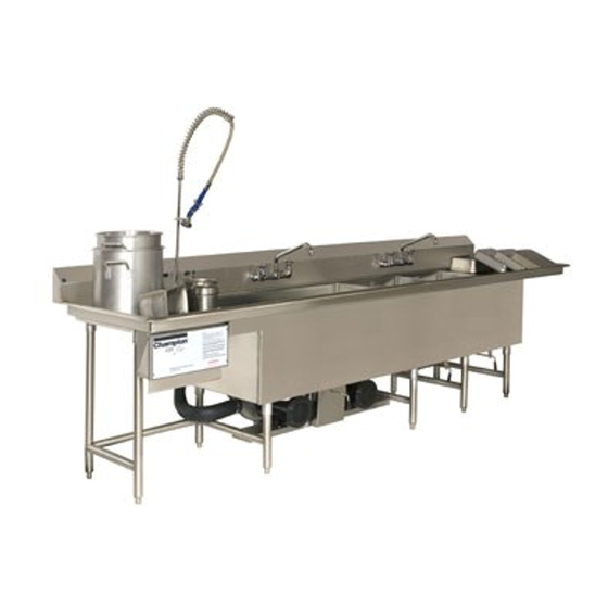
- Page 1 P.O. Box 4149 Winston Salem, NC 27115-4149 336/661-1556 Fax:: 336/661-1660 Technical Manual Taskmaster Power Wash Sink System Model PP-3 Machine Serial No. www.championindustries.com 2674 N. Service Road Jordan Station, Ontario, Canada L0R 1S0 905/562-4195 Fax: 905/562-4618...
- Page 2 This Page Intentionally Left Blank...
- Page 3 U S E R M A N U A L Operation & Installation Guide Champion Industries PO Box 4149 Winston Salem, NC 27115 336/661-1556 www.championindustries.com...
-
Page 4: Table Of Contents
TABLE OF CONTENTS NOTES... E INITIAL START UP... 6 ... 6 ANKS WITH ATER ... 6 HEMICALS ... 7 PPROVED HEMICALS OPERATION INSTRUCTIONS... 8 ... 8 CRAPPING ... 8 OADING Pots and Pans... 8 Utensils and Silver Ware... 9 Sheet Pans... 9 ... - Page 5 AL2 State...24 Trouble Shooting... 25 DELUXE C ... 26 ONTROL ENTER Display ... 26 Mylar Buttons... 26 Cycle Buttons ...26 Stop Button...27 Language Buttons ...27 Up/Down Buttons ...27 Mylar Indicator Lights...28 Basic Operation ... 28 Time Display ... 29 Wash Cycles ... 29 Change Settings ...29 Step Duration...30 Step Temperature...30...
- Page 6 Wire Diagrams... 43 DELUXE – 208V w/Communications ...43 DELUXE – 480V w/Communications ...43 DELUXE – 480V w/Communications ...44 Wash Cycle Defaults ... 45 NOTES... 47 INSTALLATION ... 48 ... 48 NSTALLATION ... 48 LACEMENT ... 49 LUMBING EQUIREMENTS ... 49 LECTRICAL EQUIREMENTS WARRANTY INFORMATION ...
-
Page 7: Initial Start Up
S T A R T INITIAL START UP Fill Tanks with Water WASH TANK – Fill wash tank with hot water to the marked Fill Line. The water temperature ought to be approximately 110˚ to 120˚ F (43˚ to 49˚ C). RINSE TANK –... -
Page 8: Approved Chemicals
S T A R T Approved Chemicals It is recommended that chemicals that are low to non foaming, metal safe, and non- caustic be used in the wash and sanitize tank. Caustic chemicals are capable of burning, corroding, or destroying living tissue and should not be used. -
Page 9: Operation Instructions
O P E R A T I O N I N S T R U C T I O N S OPERATION INSTRUCTIONS Pre-Scrapping It is recommended that any loose or excess soils be removed from the item to be washed prior to placing it into the wash tank. -
Page 10: Utensils And Silver Ware
O P E R A T I O N I N S T R U C T I O N S Utensils and Silver Ware Utensils and Silver Ware must be placed in a utensil basket. If your unit was not supplied with a utensil basket, one can be ordered from the factory. -
Page 11: Unload Wash Tank
O P E R A T I O N I N S T R U C T I O N S Unload Wash Tank The display will indicate that the items are clean when a wash cycle has been completed. At this time the system will switch to a holding cycle. -
Page 12: Notes
O P E R A T I O N I N S T R U C T I O N S NOTES... -
Page 13: Control Panels
There are two types of control panels used, the STANDARD and the DELUXE. Your control box type is printed on the front cover. Use the diagrams below to determine which the diagrams below to determine which control box you have. control box you have. STANDARD CONTROL CENTER Champion DELUXE CONTROL CENTER... -
Page 14: Standard Control Center
C O N T R O L P A N E L S STANDARD Control Center Mylar Buttons Temp Button , press to set or display the wash tanks running temperature. When pressed, the display will toggle between sp and 115 (115 represents a temperature set point value and may be different from your display), at this time you can press the Up and Down Arrow keys to change the set point temperature. -
Page 15: Mylar Indicator Lights
C O N T R O L P A N E L S Mylar Indicator Lights The heater light will illuminate whenever the wash tank’s heater is powered on. The alarm light will illuminate whenever an alarm has occurred. The change water indicator light will flash when it is time to change water. -
Page 16: Advanced Operation
C O N T R O L P A N E L S Advanced Operation Changing Temperature Set Point The temperature set point is the water temperature setting for the wash tank and is the only parameter that can be set by the operator. If the TEMP button is pressed once, the display will switch back and forth from sp and 115 (115 represents the temperature setting and may be different from your display). -
Page 17: Configuration Mode -C N F
C O N T R O L P A N E L S Parameter Parameter Description Mnemonic Name Setpoint Temperature Set Point Change Water Cycle Timer 1 Soap Dispensing Delay Timer 2 Timer 3 Soap Dispensing Time Alarm 1 Alarm 1 Set Point Al.1 Hysteresis Alarm 1 Hysteresis... -
Page 18: Loading Celsius Or Fahrenheit Tables
C O N T R O L P A N E L S Parameter Description Mnemonic Input table Low scale range of sensors High scale range of sensors Output 1 control action Output 2 function Output 2 alarm type Alarm 1 standby function Auto-ranging display Filter sensor values P1 2... -
Page 19: Display Software Version
C O N T R O L P A N E L S Display Software Version To display the software version, enter the configuration mode (See instructions listed in the Configuration Mode – cnf section listed above). When cnf is displayed, press the DOWN button. -
Page 20: Timer Operation
C O N T R O L P A N E L S Timer Operation The change water timer (t) will retain its current count when the washer is stopped or when power has been disconnected from the controller. The soap delay timer (t2) allows for a delay before soap is dispensed into the wash tank. This will allow the soap to be added to a wash tank when it is full of water and the circulation pumps are running. -
Page 21: Wire Diagrams
C O N T R O L P A N E L S Wire Diagrams agrams STANDARD – 208V STANDARD – 208V POWER INCOMING PHASE VOLT Z361403GE... -
Page 22: Standard - 480V
C O N T R O L P A N E L S STANDARD – 480V POWER INCOMING PHASE VOLT .750 Primary volts phase single volts Z361403GE... -
Page 23: Operational Details And Engineering Diagram
C O N T R O L P A N E L S Operational Details and Engineering Diagram UP + START/STOP Buttons pressed for 15 seconds Drain STATE • Display shows drn • Change Water Light flashes • Heater is enabled •... -
Page 24: Operation Modes
C O N T R O L P A N E L S Operation Modes Fill State This mode is entered when the operator drains the water, and as part of the Change Water procedure, a Dry Fire has occurred. Display shows fil Change Water indicator light is OFF Alarm indicator light is on until al. -
Page 25: Drain State
C O N T R O L P A N E L S Drain State When the timer t expires, the controller will change from the RUN STATE to the DRAIN STATE. Display shows drn Change Water indicator light flashes Heater is enabled Pumps are OFF Soap Pump is disabled... -
Page 26: Trouble Shooting
C O N T R O L P A N E L S When AL.2 clears, the controller returns to the RUN or STOP STATE. Display shows the process value Alarm indicator light is OFF Heater is enabled Pump is enabled If the controller is returning to a RUN STATE, then time t will resume If alarm AL.1 is activated, the controller will automatically be placed into the FILL STATE. -
Page 27: Deluxe Control Center
C O N T R O L P A N E L S DELUXE Control Center Champion Display In general, all messages are scrolled in the upper display box at about 2 characters per second, while the temperature is displayed in the lower display box. There are LED icons to indicate various system states. -
Page 28: Stop Button
C O N T R O L P A N E L S Stop Button A normal press of this key stops the current cycle if one is active. If the unit is currently in the Hold Mode, pressing the Stop key will turn off the unit. If the unit is currently in the Off Mode, a 2-second long press of this key will activate the Manual Drain function. -
Page 29: Mylar Indicator Lights
C O N T R O L P A N E L S Mylar Indicator Lights The soap indicator light will be lit up when the soap pump is on The heater indicator light will be lit up when the heater is on The pump speed indicator lights will be “rotating”... -
Page 30: Time Display
C O N T R O L P A N E L S In the PAUSE state, the wash cycles timer is stopped and the circulation pumps are shut off. The heater is still working to maintain temperature. Pressing the cycle’s key again will continue the cycle. -
Page 31: Step Duration
C O N T R O L P A N E L S The cycle LED will light up and the first setting S T E P 1 D U R A T I O N will scroll on the display, and alternate every 5 seconds with its value. -
Page 32: Step Soap Quantity
C O N T R O L P A N E L S Step Soap Quantity This setting allows soap quantity control for the step. Setting name: S T E P X S O A P Q U A N T I T Y Allowed values: M I N , I N T , M A X Default value: M I N System States... -
Page 33: Off State
C O N T R O L P A N E L S Off State This state is active after filling up the tank with water and pressing the STOP key following the POWER UP state. This is also the state that becomes active whenever the Stop key is pressed during a wash cycle. -
Page 34: Hold/Clean State
C O N T R O L P A N E L S Hold/Clean State In this state, there is water in the tank, and its temperature is maintained at the Hold Temperature. The pump speed in this mode is determined by the Hold Pump Speed. The purpose of the Hold mode is to keep the dirt from settling back onto the dishes and also serves to keep the oily water and soap from separating between washes. -
Page 35: Soap Level Detection
C O N T R O L P A N E L S Soap Level Detection This is an optional feature that your system may not be equipped with. There are 2 inputs that allow connection to external dry contacts that allow detection of 2 soap levels. Soap Level #1 input warns of low soap levels, and Soap Level #2 warns that there is no more soap. -
Page 36: Auto-Drain / Fill
C O N T R O L P A N E L S Auto-Drain / Fill The Auto drain/fill feature is an optional feature and requires extra solenoid valves. Once the Auto-Drain/Fill key is accepted, the following sequence of events occurs: The unit decides if there really is water in the wash tank (using Dry-Fire detection feature). -
Page 37: Temperature Probe Error
C O N T R O L P A N E L S Temperature Probe Error All probes are typically type-K probes. All temperature readings normally associated with a type-K probe are considered valid by the controller. However, if the probes become disconnected or otherwise open, the controller will sound the buzzer and scroll T E M P E R A T U R E P R O B E E R R O R on line 1 of the display. -
Page 38: Omron Inverter Control
C O N T R O L P A N E L S Omron Inverter Control The Omron Inverter Control inside the DELUXE panel allows for speed control of the 3- phase AC water pumps. For the Omron and the controller to communicate with each other the Omron will need the following parameters set. -
Page 39: Temperature Units
C O N T R O L P A N E L S The parameters that can be changed follow: Temperature Units This setting allows a different temperature unit to be used for display. You can switch between Celsius and Fahrenheit. Parameter name: T E M P E R A T U R E U N I T S Allowed values: C or F Factory default: F... -
Page 40: Hold Temperature
C O N T R O L P A N E L S Hold Temperature This setting sets the water temperature for the Hold or Clean state. Parameter name: H O L D T E M P E R A T U R E Allowed values: 1 0 0 ˚... -
Page 41: Sanitize Heater Temperature
C O N T R O L P A N E L S Sanitize Heater Temperature This setting sets the water temperature for the Sanitize tank. Parameter name: H E A T E R 2 T E M P E R A T U R E Allowed values: O F F , and 1 0 0 e to 2 0 0 e (3 8 Factory default: O F F Buzzer Time... -
Page 42: Dry Fire Threshold
C O N T R O L P A N E L S Dry Fire Threshold This is the maximum allowed temperature that heater sheath can attain. When this is reached, the control assumes the tank has been drained and goes to the Power-up state. Parameter name: D R Y F I R E T H R E S H O L D Allowed values: 1 2 5 ˚... -
Page 43: Operational Details And Engineering Diagram
C O N T R O L P A N E L S Operational Details and Engineering Diagram Auto-Fill Dry-Fire Auto-Drain or Manual Drain Dry-Fire Dry-Fire Power-Up Stop/Cycle state long press Tub Fill Cycle programming Off state Stop/Cycle long press Cycle key press Cycle... -
Page 44: Wire Diagrams
C O N T R O L P A N E L S Wire Diagrams DELUXE – 208V w/Communications POWER INCOMING PHASE VOLT R/L2 T/L1 S/L3 ECM1-1-A1TK-A3TK-011-021-031-041-SHU-BZ-IR-RM-SS1... -
Page 45: Deluxe - 480V W/Communications
C O N T R O L P A N E L S DELUXE – 480V w/Communications POWER INCOMING PHASE VOLT Switch Disk Thermal Adj. R/L1 T/L2 S/L3 .750 Primary volts phase single volts ECM1-1-A1TK-A3TK-011-021-031-041-SHU-BZ-IR-RM-SS1 K 5000 - 480V DELUXE – 480V w/Communications w/Communications Heater... -
Page 46: Wash Cycle Defaults
C O N T R O L P A N E L S Wash Cycle Defaults English French LE CYCLE DE MARCHANDISE DELICAT Spanish Italian STEP 1 Duration 5 : 0 0 1 1 5 ˚ f Temperature Pump Speed L O W Soap Amount M I N... - Page 47 C O N T R O L P A N E L S English French Spanish Italian Duration Temperature Pump Speed Soap Amount NOTE TIME DISPLAY : See the English French Spanish Italian Duration Temperature Pump Speed Soap Amount Cycle 4 Name POTS AND PANS CYCLE CYCLE DE POTS ET CASSEROLAS...
-
Page 48: Notes
C O N T R O L P A N E L S NOTES... -
Page 49: Installation
I N S T A L L A T I O N INSTALLATION Pre-Installation REVIEW – Review all of the instructions prior to installation. INSTALLATION – Installation should be performed by licensed and certified plumbers & electricians. WORK – All work should be conformed to all local, state, and national regulatory agency requirements. -
Page 50: Plumbing Requirements
I N S T A L L A T I O N Plumbing Requirements WATER SUPPLY – Hot and Cold Water should be supplied by ½” or ¾” water lines, with the ¾” being the preferred method. DRAINS – A 1-1/2” minimum waste connection is required. -
Page 51: Warranty Information
M A I N T E N A N C E WARRANTY INFORMATION Warranty Your pot scrubbing sink is designed and built to deliver many years of trouble free operation. All units have a one-year labor warranty and a five-year workmanship guarantee. -
Page 52: Notes
M A I N T E N A N C E NOTES... -
Page 53: Maintenance
M A I N T E N A N C E MAINTENANCE Routine Maintenance Heater The heating element must be cleaned once every thirty days to ensure maximum heater life. The element is located at the back of the wash tank behind the intake grating and can be cleaned with a scouring pad. -
Page 54: Replacing Thermocouple
M A I N T E N A N C E Carefully pull the heater and wires out, exposing the electrical connections. Disconnect the electrical Connections. Remove the gasket. Get the new heater and slide the gasket over the wires. Connect the electrical connection and slide the wires and heater into position. -
Page 55: Replacing Standard Electronics
M A I N T E N A N C E Connect the electrical connection and slide the wires and thermocouple into position. Install and tighten the clamp. Install the perforated cover. Turn on the main power. Replacing STANDARD Electronics Turn off and lockout the incoming power to the control panel. -
Page 56: Replacing Deluxe Controller
M A I N T E N A N C E Remove the component plate Insert the new component plate. Install the four fasteners to secure the component plate. Plug in the four black plugs and the one yellow plug. Reconnect the incoming power to the terminal block. -
Page 57: Replacing Pump
M A I N T E N A N C E Remove the old controller and install the new one. Install the five retainers “C”. Connect the three plugs “B”. Connect the four Plugs “A” Close the hinged panel and replace the two fasteners. Turn on Power. -
Page 58: Replacing Soap Pump
M A I N T E N A N C E Replacing Soap Pump Turn off and lockout the incoming power to the control panel. Disconnect power cord “A” Disconnect Hoses “B” Remove the two retainers “C” Replace Pump Install the two retainers “C” Connect the two hoses “B”... -
Page 59: Parts List
P A R T S L I S T Parts List Heater / Thermocouple Image 2500 watt heater 5000 watt heater 7000 watt heater Water temperature (for HTR25, HTR50, HTR70, and WTTC) (for HTR25, HTR50, HTR70, and WTTC) Description Part Number HTR-25 HTR-50 HTR-70... -
Page 60: Soap Pump / Standard / Deluxe
P A R T S L I S T Soap Pump / STANDARD / DELUXE Image Description Soap Pump STANDARD 208V Plug-N-Play Board STANDARD 480V Plug-N-Play Board DELUXE 208V Plug-N-Play Board DELUXE 480V Plug-N-Play Board DELUXE Controller Part Number SP-1600 K1-208 K1-480 K5-208... -
Page 61: Water Pump
P A R T S L I S T Water Pump Image Description Pump Assembly 208V Left Side Pump Assembly 208V Right Side Pump Assembly 480V Left Side Pump Assembly 480V Right Side Pump Motor 208V Pump Motor 480V Pump Housing Pump Impeller Part Number PA-208L... - Page 62 P A R T S L I S T Image Description Pump Backing Plate Pump O-Ring Pump Seal Pump Discharge Hose – Left Side Pump Discharge Hose – Right Side Intake Hose Hose Clamp Part Number PBP-01 POR-01 PS-01 PDH-L PDH-R IH-01 HC-01...
- Page 63 P A R T S L I S T NOTES...
- Page 64 P A R T S L I S T NOTES...
-
Page 65: Notes
P A R T S L I S T NOTES... - Page 67 Champion Industries PO Box 4149 Winston Salem, NC 27115 336/661-1556 www.championindustries.com...
Need help?
Do you have a question about the Taskmaster PP-3 and is the answer not in the manual?
Questions and answers