Table of Contents
Advertisement
®
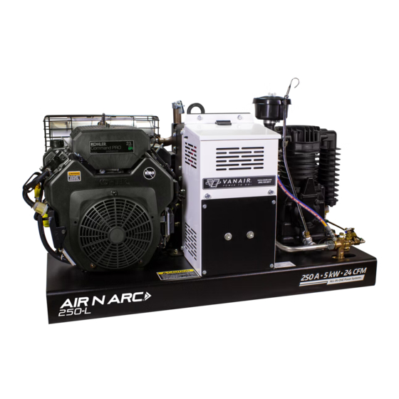
ALL-IN-ONE POWER SYSTEMS
WELDER • GENERATOR • AIR COMPRESSOR • BATTERY BOOSTER
OPERATION MANUAL & PARTS LIST
NOTE:
THIS EXCERPT IS THE AIR-N-ARC 250 ADDENDUM TO
THE AIR-N-ARC 200 MANUAL.
Vanair Manufacturing, Inc.
Vanair Manufacturing, Inc.
10896 West 300 North
Phone: (219) 879-5100
Michigan City, IN 46360
(800) 526-8817
Addendum 090044_r0
Service Fax: (219) 879-5335
to Manual 090019-OP_r0
Parts Fax: (219) 879-5340
www.vanair.com
Effective Date:
Sales Fax: (219) 879-5800
4-2013
©2013 Vanair Manufacturing, Inc.
All rights reserved
Advertisement
Table of Contents
Troubleshooting

Related Manuals for Vanair AIR N ARC RELIANT 250 Series


Summary of Contents for Vanair AIR N ARC RELIANT 250 Series
- Page 1 10896 West 300 North Phone: (219) 879-5100 Michigan City, IN 46360 (800) 526-8817 Addendum 090044_r0 Service Fax: (219) 879-5335 to Manual 090019-OP_r0 Parts Fax: (219) 879-5340 www.vanair.com Effective Date: Sales Fax: (219) 879-5800 4-2013 ©2013 Vanair Manufacturing, Inc. All rights reserved...
- Page 2 ® ® ADDENDUM AIR N ARC 250 SERIES ALL-IN-ONE POWER SYSTEM THE FOLLOWING ARE CHANGES IN SPECIFICATIONS THAT AFFECT THE AIR-N-ARC 250: 1. RATED WELDER OUTPUT 250A high Frequency DC/CC, DC/CV, 100% duty Cycle @ 250 Amps 2. OIL CAPACITY 2 Quarts 3.
- Page 3 ® ® AIR N ARC 250 SERIES ALL-IN-ONE POWER SYSTEM ADDENDUM BLANK PAGE Addendum 090044 PAGE III...
- Page 4 ® ® ADDENDUM AIR N ARC 250 SERIES ALL-IN-ONE POWER SYSTEM 9.6 ENGINE AND DRIVE PARTS 16 10 PA6100021ID_r0 Addendum 090044 PAGE IV...
- Page 5 9.6 ENGINE AND DRIVE PARTS ITEM DESCRIPTION PART NUMBER CAP, RAIN 1-1/4” EXHAUST 262706 CLAMP, EXHAUST 1-1/4 REV.0 262906 CLAMP, LOOM #010 5/8” 268503 KEY, SQUARE 1/4 x 1/4 x 3 821104-300 CAPSCREW, HEX GR5 1/4-20 x 1-1/4 829104-125 CAPSCREW, HEX GR5 3/8-16 x 1.50 829106-150 CAPSCREW, HEX GR5 3/8-16 x 1.75 829106-175...
- Page 6 Vanair Manufacturing, Inc. 10896 West 300 North Michigan City, IN 46360 Phone: (219) 879-5100 (800) 526-8817 Service Fax: (219) 879-5335 Parts Fax: (219) 879-5340 Sales Fax: (219) 879-5800 www.vanair.com Printed in the U.S.A. Specifications Subject to Change Without Prior Notice...
-
Page 7: Warranty
WELDER • GENERATOR • AIR COMPRESSOR • BATTERY BOOSTER OPERATION MANUAL & PARTS LIST NOTE NOTE NOTE Making unauthorized modifications to Use only Genuine Vanair Parts. the system components WILL VOID THE Inspect and replace damaged WARRANTY! components before operation. Substituting non-Vanair... - Page 8 TO THE GREAT EXTENT PERMITTED BY APPLICABLE LAW, THE REMEDIES PROVIDED HEREIN ARE THE SOLE AND EXCLUSIVE Vanair must be noti ed in writing within thirty (30) days of any REMEDIES APPLICABLE TO THE VANAIR EQUIPMENT. IN NO such defect or failure. No warranty work or returns without prior EVENT SHALL VANAIR BECOME LIABLE FOR DIRECT, INDIRECT, authorization is allowed.
-
Page 9: Table Of Contents
AIR COMPRESSOR TERMS AND DEFINITIONS ................VIII WARRANTY CLAIMS PROCEDURE ......XI CLAIMS PROCESS FOR WARRANTED PARTS..................XI PROCEDURE ............................XI INTRODUCTION..............1 EXPERIENCE THE VANAIR ADVANTAGE .....................1 A NOTE ON MANUAL NAVIGATION ......................2 SECTION 1: SAFETY ............3 GENERAL INFORMATION ......................3 DANGERS, WARNINGS, CAUTIONS, AND NOTES ..............3 INTERNATIONAL SAFETY SYMBOL ....................4... -
Page 10: Table Of Contents
® ® TABLE OF CONTENTS AIR N ARC 200 SERIES ALL-IN-ONE POWER SYSTEM SECTION 1: SAFETY (CONTINUED) 1.4.11 CYLINDERS CAN EXPLODE IF DAMAGED .......................9 ENGINE HAZARDS ........................10 1.5.1 BATTERY EXPLOSION CAN BLIND ........................10 1.5.2 FUEL CAN CAUSE FIRE OR EXPLOSION ......................10 1.5.3 MOVING PARTS CAN CAUSE INJURY ......................11 1.5.4... - Page 11 ® ® AIR N ARC 200 SERIES ALL-IN-ONE POWER SYSTEM TABLE OF CONTENTS SECTION 2: DESCRIPTION ..........22 FIGURE 2-1: MAJOR MACHINE COMPONENTS LOCATIONS.............20 2.1 GENERAL DESCRIPTION ........................22 2.2 COMPRESSED AIR SYSTEM......................22 2.2.1 COMPRESSOR UNIT ............................... 22 2.2.2 AIR INTAKE / AIR FILTER ..........................23 2.2.3 PRESSURE RELIEF VALVE ..........................
- Page 12 ® ® TABLE OF CONTENTS AIR N ARC 200 SERIES ALL-IN-ONE POWER SYSTEM SECTION 4: INSTALLATION (CONTINUED) INSTALLATION AND DIMENSIONS DIAGRAM (PART 1 OF 2) ........... 39 INSTALLATION AND DIMENSIONS DIAGRAM (PART 2 OF 2) ........... 40 SECTION 5: OPERATION ..........41 GENERAL INFORMATION ......................
- Page 13 ® ® AIR N ARC 200 SERIES ALL-IN-ONE POWER SYSTEM TABLE OF CONTENTS SECTION 6: MAINTENANCE (CONTINUED) 6.5.3.2 ................69 RESSURE ALVE EPLACEMENT 6.5.3.3 ................70 RESSURE ALVE AINTENANCE 6.5.3.4 ................71 RESSURE ALVE EPLACEMENT 6.5.4 COMPRESSOR HEAD VALVE ASSEMBLY INSPECTION AND MAINTENANCE..........72 6.5.4.1 ....................
- Page 14 ® ® TABLE OF CONTENTS AIR N ARC 200 SERIES ALL-IN-ONE POWER SYSTEM SECTION 7: TROUBLESHOOTING (CONTINUED) A NOTE ON CONDENSATION DUE TO COMPRESSION ............100 TROUBLESHOOTING GUIDE ....................100 SECTION 8: DIAGRAMS ..........111 GENERAL INFORMATION ......................111 WIRING DIAGRAM - AIR N ARC 200 SERIES ................112 WIRING DIAGRAM - SWITCHES &...
-
Page 15: Glossary
® ® AIR N ARC 200 SERIES ALL-IN-ONE POWER SYSTEM GLOSSARY GLOSSARY: TERMS AND DEFINITIONS G.1 GENERAL TERMS AND Constant Current (CC) Welding Machine - These welding machines have limited DEFINITIONS maximum short circuit current, with consistent amperage regardless of the Air/Oil Separator - Coalescer element. -
Page 16: Air Compressor Terms And Definitions
® ® GLOSSARY AIR N ARC 200 SERIES ALL-IN-ONE POWER SYSTEM minutes and then must be allowed to cool work. This process can cut all metals that with the fan motor running for 4 minutes. conduct electricity. Pounds Per Square Inch (psi) - A Flux Cored Arc Welding (FCAW) - An arc welding process which melts and joins measurement equal to a mass or weight... - Page 17 ® ® AIR N ARC 200 SERIES ALL-IN-ONE POWER SYSTEM GLOSSARY compression is completed. They are one of Pump - Part that compresses the air and the most effective means of removing pushes it into the tank. moisture from compressed air. Reciprocating Air Compressors - those in Air Receivers - tanks into which the which each compressing element consists of...
- Page 18 ® ® GLOSSARY AIR N ARC 200 SERIES ALL-IN-ONE POWER SYSTEM BLANK PAGE PAGE - X 090019-OP_r0...
-
Page 19: Warranty Claims Procedure
RMA is void and any claims will be final determination as to the item’s warranty status. denied. 6. Vanair will need a P.O. or credit card number to cover the cost of the part and shipping before sending a part to a customer for warranty consideration. - Page 20 ® ® WARRANTY PROCEDURE AIR N ARC 200 SERIES ALL-IN-ONE POWER SYSTEM 800-526-8817 www.vanai r.com MODEL NUMBER SERIAL NUMBER PSIG MAXIMUM PRE SSURE COMPRE SSOR INPUT RPM 260940 Figure W-1: Machine Serial Number Location Figure W-2: Engine Serial Number Location PAGE - XII 090019-OP_r0...
- Page 21 All paper work associated with the returned item and warranty repair cost must reference the RMA number issued against the part, and be forwarded to Vanair within 30 days of the completion of work. 090019-OP_r0 PAGE - XIII...
- Page 22 ® ® WARRANTY PROCEDURE AIR N ARC 200 SERIES ALL-IN-ONE POWER SYSTEM BLANK PAGE PAGE - XIV 090019-OP_r0...
-
Page 23: Introduction
POWER SYSTEM Due to the caustic nature of “un-sealed” ADVANTAGE! ® lead acid batteries Vanair Mfg., Inc. The Air N Arc All-In-One Power System is designed to does not recommend the use of this style of battery. Acid fumes can cause damage provide compressed air, DC welding output, AC power, to the machine and void the warranty. -
Page 24: A Note On Manual Navigation
Manufacturing, Inc. takes no responsibility for errors or consequential damages caused by reliance on the information contained herein. Vanair Manufacturing, Inc. reserves the right to make design change modifications or improvements without prior notification. A NOTE ON MANUAL LAYOUT NAVIGATION Refer to Figure M-1. -
Page 25: Section 1: Safety
SECTION 1: SAFETY 1.1 GENERAL INFORMATION IMPORTANT ® The products provided by Vanair Manufacturing, Inc., are designed and manufactured for safe operation and maintenance. But it is ultimately the responsibility of the users and maintainers for safe use of this equipment. -
Page 26: International Safety Symbol
® ® SECTION 1: SAFETY AIR N ARC 200 SERIES ALL-IN-ONE POWER SYSTEM 1.3 INTERNATIONAL SAFETY SYMBOL The symbols shown and defined in Section 1: Safety are used throughout this manual to call attention to and identify possible hazards. The international warning symbol shown above is used on all decals, labels and signs that concern information pertaining to bodily harm. - Page 27 ® ® AIR N ARC 200 SERIES ALL-IN-ONE POWER SYSTEM SECTION 1: SAFETY Do not work alone! Disconnect input power or stop engine before installing or servicing this equipment. Lockout/tag out input power according to OSHA29 CFR1910.147 (see Section 1.9, Principal Safety Standards).
-
Page 28: Fumes And Gases Can Be Hazardsous
® ® SECTION 1: SAFETY AIR N ARC 200 SERIES ALL-IN-ONE POWER SYSTEM 1.4.2 FUMES AND GASES CAN BE HAZARDOUS Welding produces fumes and gases. Breathing these fumes and gases can be hazardous to your health. Keep your head out of the fumes. Do not breathe the fumes. -
Page 29: Enclosed Spaces Can Cause Abuild-Up Of Noxious Fumes And Overheating
® ® AIR N ARC 200 SERIES ALL-IN-ONE POWER SYSTEM SECTION 1: SAFETY 1.4.4 ENCLOSED SPACES CAN CAUSE A BUILD-UP OF NOXIOUS FUMES AND OVERHEATING Do not use in enclosed spaces where deadly exhaust gases can build up and machine can overheat, causing fire. 1.4.5 ARC RAYS CAN BURN EYES AND SKIN Arc rays from the welding process... -
Page 30: Flying Metal Can Injure Eyes
® ® SECTION 1: SAFETY AIR N ARC 200 SERIES ALL-IN-ONE POWER SYSTEM Do not weld where flying sparks can strike flammable material. Protect yourself and others from flying sparks and hot metal. Be alert that welding sparks and hot materials from welding can easily go through small cracks and openings to adjacent areas. -
Page 31: Hot Parts Can Cause Severe Burns
® ® AIR N ARC 200 SERIES ALL-IN-ONE POWER SYSTEM SECTION 1: SAFETY 1.4.8 HOT PARTS CAN CAUSE SEVERE BURNS Do not touch hot parts bare handed. Allow cooling period before working on equipment. 1.4.9 NOISE CAN DAMAGE HEARING To handle hot parts, use proper tools and/or wear heavy, insulated welding gloves and clothing to prevent burns. -
Page 32: Engine Hazards
® ® SECTION 1: SAFETY AIR N ARC 200 SERIES ALL-IN-ONE POWER SYSTEM Use only correct shielding gas cylinders, regulators, hoses, and fittings designed for the specific application; maintain them and associated parts in good condition. Turn face away from valve outlet when opening cylinder valve. -
Page 33: Moving Parts Can Cause Injury
® ® AIR N ARC 200 SERIES ALL-IN-ONE POWER SYSTEM SECTION 1: SAFETY 1.5.3 MOVING PARTS CAN CAUSE INJURY Keep away from fans, belts, and rotors. Keep all doors, panels, covers, and guards closed and securely in place. Stop engine before installing connecting unit. -
Page 34: Battery Acid Can Burn Skin And Eyes
® ® SECTION 1: SAFETY AIR N ARC 200 SERIES ALL-IN-ONE POWER SYSTEM 1.5.7 BATTERY ACID CAN BURN SKIN AND EYES Do not tip battery. Replace damaged battery. Flush eyes and skin immediately with water. 1.5.8 ENGINE HEAT CAN CAUSE FIRE Do not locate unit on, over, or near combustible surfaces or flammables. -
Page 35: Compressed Air Can Cause Injury
® ® AIR N ARC 200 SERIES ALL-IN-ONE POWER SYSTEM SECTION 1: SAFETY 1.6.3 COMPRESSED AIR CAN CAUSE INJURY Wear approved safety goggles. Do not direct air stream toward self or others. 1.6.4 TRAPPED AIR PRESSURE AND WHIPPING HOSES CAN CAUSE INJURY Release air pressure from tools and system before servicing, adding or changing... -
Page 36: Additional Symbols For Installation, Operation And Maintenance
® ® SECTION 1: SAFETY AIR N ARC 200 SERIES ALL-IN-ONE POWER SYSTEM 1.7 ADDITIONAL SYMBOLS FOR INSTALLATION, OPERATION AND MAINTENANCE 1.7.1 FALLING UNIT CAN CAUSE INJURY Use lifting bail to lift unit and properly installed accessories only. Lift and support unit only with proper equipment and correct procedures. -
Page 37: Enclosed Spaces Can Cause Abuild-Up Of Noxious Fumes And Overheating
® ® AIR N ARC 200 SERIES ALL-IN-ONE POWER SYSTEM SECTION 1: SAFETY 1.7.5 ENCLOSED SPACES CAN CAUSE A BUILD-UP OF NOXIOUS FUMES AND OVERHEATING Do not use in enclosed spaces where deadly exhaust gases can build up and machine can overheat, causing fire. 1.7.6 TILTING OF TRAILER CAN CAUSE INJURY Use tongue jack or blocks to support... -
Page 38: Arc Welding Can Cause Interference
® ® SECTION 1: SAFETY AIR N ARC 200 SERIES ALL-IN-ONE POWER SYSTEM grounding and shielding to minimize the possibility of interference. 1.7.9 ARC WELDING CAN CAUSE INTERFERENCE Electromagnetic energy can interfere with sensitive electronic equipment such as microprocessors, computers, and computer-driven equipment such as robots. -
Page 39: Principal Safety Standards
® ® AIR N ARC 200 SERIES ALL-IN-ONE POWER SYSTEM SECTION 1: SAFETY PRINCIPAL SAFETY STANDARDS Safety in Welding, Cutting, and Allied Processes, ANSI Standard Z49.1, from Global Engineering Documents (phone: 1-877-413-5184, website:www.global.ihs.com). Recommended Safe Practices for the Preparation for Welding and Cutting of Containers and Piping, American Welding Society Standard AWSF4.1, from Global Engineering Documents (phone: 1-877-413-5184, web... -
Page 40: Emf Information
® ® SECTION 1: SAFETY AIR N ARC 200 SERIES ALL-IN-ONE POWER SYSTEM 1.10 EMF INFORMATION Considerations About Welding And The Effects Of Low Frequency Electric And Magnetic Fields Welding current, flows through welding cables, will cause electromagnetic fields. There has been and still is some concern about such fields. -
Page 41: Disposing Of Machine Fluids
Decal Section (Section 9.11) of this manual. 1.12 DISPOSING OF MACHINE FLUIDS Always dispose of machine fluids under the guidance of all applicable local, regional and/or federal law. Vanair encourages recycling when allowed. additional information, consult the container for information. - Page 42 ® ® SECTION 2: DESCRIPTION AIR N ARC 200 SERIES ALL-IN-ONE POWER SYSTEM Figure 2-1: MAJOR MACHINE COMPONENTS LOCATIONS 090019-OP_r0 page - 20...
- Page 43 ® ® AIR N ARC 200 SERIES ALL-IN-ONE POWER SYSTEM SECTION 2: DESCRIPTION FIGURE 2-1: MAJOR MACHINE COMPONENTS LOCATIONS KEY DESCRIPTION INSTRUMENT PANEL SERVICE AIR OUTLETS LIFTING BAIL FUEL FILL (Remote Mount) ENGINE AIR FILTER MUFFLER ENGINE OIL FILL PORT ENGINE OIL FILTER ENGINE OIL DRAIN PRESSURE SWITCH...
-
Page 44: Section 2: Description
200 SERIES ALL-IN-ONE POWER SYSTEM SECTION 2: DESCRIPTION 2.1 GENERAL DESCRIPTION NOTE ® Vanair Manufacturing, Inc.’s Air N Arc 200 Series All-In- One Power System offers superior performance and reliability, as well as limited maintenance requirements. The Power System package is designed to provide... -
Page 45: Air Intake / Air Filter
® ® AIR N ARC 200 SERIES ALL-IN-ONE POWER SYSTEM SECTION 2: DESCRIPTION high pressure air as an automatic feature of the 200 Series machine package. Whenever the pressure in the air tank drops below 150 psi, the engine will run at full throttle until the pressure in the 30 gallon capacity standard tank reaches 175 psi. -
Page 46: Pressure Relief Valve
® ® SECTION 2: DESCRIPTION AIR N ARC 200 SERIES ALL-IN-ONE POWER SYSTEM for maintenance schedules, and Section 6.5.1 for specific air filter maintenance procedures. 2.2.3 PRESSURE RELIEF VALVE See Figure 2-4. The pressure relief valve is the last safety device that will be activated. It is a spring-backed normally closed valve that will vent excess pressures to the atmosphere when excessive pressures are reached. -
Page 47: Engine
® ® AIR N ARC 200 SERIES ALL-IN-ONE POWER SYSTEM SECTION 2: DESCRIPTION The pressure in the air tank may override the manual shutdown condition of the pilot valve: The regulator valve, which is set to 10 psi, will signal the compressor to operate, running the engine at full throttle (regardless of the position of the pilot valve switch) if the pressure in the tank is below 10 psi. -
Page 48: Ac Generator
® ® SECTION 2: DESCRIPTION AIR N ARC 200 SERIES ALL-IN-ONE POWER SYSTEM DESCRIPTION DESCRIPTION ENGINE AIR FILTER ENGINE DIPSTICK HANDLE INNER AIR FILTER COVER Acceptable range for engine oil level between: (FULL), and F (LOW) - DO NOT OVERFILL PRE-FILTER ELEMENT AIR FILTER ELEMENT ENGINE OIL FILTER... -
Page 49: Instrumentation
® ® AIR N ARC 200 SERIES ALL-IN-ONE POWER SYSTEM SECTION 2: DESCRIPTION maintenance since they do not have slip rings, nor slipping contacts. The end brackets are die-cast in a high resistance aluminum alloy, the shaft is C45 steel, and is fitted with a keyed fan. - Page 50 ® ® SECTION 2: DESCRIPTION AIR N ARC 200 SERIES ALL-IN-ONE POWER SYSTEM DESCRIPTION DESCRIPTION VOLTS/AMPS DISPLAY (2.5.1) AC VOLTAGE OUTLETS (2.5.6) WELDER CC/CV TOGGLE SWITCH (2.5.2) GENERATOR CONTROL ON/OFF SWITCH (2.5.7) DC CHARGER/WELDER TOGGLE SWITCH DC CHARGER 12V / 24V TOGGLE SWITCH (2.5.2) (2.5.8) FUEL GAUGE (2.5.3)
-
Page 51: Volts/Amps Display
® ® AIR N ARC 200 SERIES ALL-IN-ONE POWER SYSTEM SECTION 2: DESCRIPTION switch, volt/amp manual adjustment dial, air pressure gauge, fuel gauge/hour meter, weld lead terminals, battery cable receptacle, generator control ON/OFF switch, AC voltage outlets, and AC overload trip/reset buttons. -
Page 52: Ac Voltage Outlets
Whenever a circuit breaker trips, always check the complete system for any possible faulty conditions before resetting the system. If trouble persists, consult Section ® 7, Troubleshooting, or the Vanair Service Department. 2.5.6 AC VOLTAGE OUTLETS The AC voltage outlets allow for AC generator power access via one 120V duplex, and one 240V receptacles. -
Page 53: Section 3: Specifications
® ® AIR N ARC 200 SERIES ALL-IN-ONE POWER SYSTEM SECTION 3: SPECIFICATIONS SECTION 3: SPECIFICATIONS TABLE 3A: WELDER, GENERATOR, AND ENGINE SPECIFICATIONS SYSTEM INFORMATION SPECIFICATION Rated Welder Output 200A High Frequency DC/CC, DC/CV; 100% Duty Cycle @ 200 Amps Welding Leads 25 or 50 Ft. - Page 54 ® ® SECTION 3: SPECIFICATIONS AIR N ARC 200 SERIES ALL-IN-ONE POWER SYSTEM TABLE 3C: UNIT WEIGHT AND DIMENSIONS SPECIFICATIONS Dimensions (Overall Package) Length (in) Width (in) Height (in) Weight (lbs) (wet) Weight (lbs) (dry) Skid-Mount 23.2 With 30 Gallon Air Tank 50.5 23.7 See Diagram 4.5 (parts 1 and 2) for full dimension drawing, and Figure 4-1 for location space requirements.
- Page 55 ® ® AIR N ARC 200 SERIES ALL-IN-ONE POWER SYSTEM SECTION 3: SPECIFICATIONS TABLE 3E: VARIOUS FUNCTION ACCEPTABLE TESTING OUTPUT RANGES FUNCTION ACCEPTABLE RANGE Engine No-Load Hi RPM 3660 +/-10 Engine Idle RPM 2000 +/-10 Air Cut-in Pressure 150 +/-10 Air Cut-out Pressure 175 +/-10 AC Generator Hz (no load)
- Page 56 ® ® SECTION 3: SPECIFICATIONS AIR N ARC 200 SERIES ALL-IN-ONE POWER SYSTEM BLANK PAGE PAGE - 34 090019-OP_r0...
-
Page 57: Section 4: Installation
Machine Package Prep page 35 NOTE Service Body Prep page 35 Machine Package Mounting page 36 Contact Vanair at (219) 879-5100 / (800) 526-8817 Installation and Dimensions Diagram 4.5 (Part 1) page 39 Service Fax: (219) 879-5335 Installation and Dimensions Diagram 4.5 (Part 2) -
Page 58: Machine Package Mounting
If mounting footprint is tighter than the desired location on the service body recommended minimum requirements, keeping it as close to the truck fuel tank consult the Vanair Service Department for application installation as possible. Mount the electric fuel pump recommendations. - Page 59 ® ® AIR N ARC 200 SERIES ALL-IN-ONE POWER SYSTEM SECTION 4: INSTALLATION 10.5” 10.5” 0.5Ø 0.5Ø 5.0” 7.5” DESCRIPTION PART NUMBER MOUNTING PATTERN WITH SPACER (SPACER) A16738P MOUNTING PATTERN WITHOUT SPACER Figure 4-2: Remote Panel Mounting Pattern (with and without Spacer) DESCRIPTION DESCRIPTION MOUNTING NUT 1/2 (x 4)
- Page 60 After such as 1/4” neoprene rubber pads. the unit has cooled, check all fluid levels and Isolating Dampeners (Part Number add as needed. PR93969) are available by calling the ® Vanair Customer Service Department. PAGE - 38 090019-OP_r0...
-
Page 61: Installation And Dimensions Diagram (Part 1 Of 2)
® ® AIR N ARC 200 SERIES ALL-IN-ONE POWER SYSTEM SECTION 4: INSTALLATION 4.5 INSTALLATION AND DIMENSIONS DIAGRAM (PART 1 OF 2) ENGINE OIL COMPRESSOR OIL DIPSTICK FILL PORT ENGINE OIL FILL ELECTRICAL FUSES AND BATTERY UNDER HOOD. 1.75 COMPRESSOR COMPRESSOR RELIEF VALVE AIR FILTER... -
Page 62: Installation And Dimensions Diagram (Part 2 Of 2)
® ® SECTION 4: INSTALLATION AIR N ARC 200 SERIES ALL-IN-ONE POWER SYSTEM 4.5 INSTALLATION AND DIMENSIONS DIAGRAM (PART 2 OF 2) 13.13 P/N A16738P 13.13 4X 5/16-18UNC 10.50 1.32 10.50 1.31 4.15 5.58 0.44 2.88 3.13 5.00 7.50 2X 1/2 NPT AIR SERVICE PORT REMOTE PANEL WITH OPTIONAL SPACER... -
Page 63: Section 5: Operation
NOTE recommendation as outlined in Section 1: Safety of this manual. WARNING ® Before starting the Vanair Air N Arc 200 All-In-One Power System, read this Before performing maintenance or repair section thoroughly and familiarize operations on the machine, ensure that... - Page 64 ® ® SECTION 5: OPERATION AIR N ARC 200 SERIES ALL-IN-ONE POWER SYSTEM DESCRIPTION DESCRIPTION VOLTS/AMPS DISPLAY AC VOLTAGE OUTLETS WELDER CC/CV TOGGLE SWITCH GENERATOR CONTROL ON / OFF SWITCH DC CHARGER/WELDER TOGGLE SWITCH DC CHARGER 12V / 24V TOGGLE SWITCH FUEL GAUGE VOLTS/AMPS MANUAL ADJUSTMENT DIAL HOUR METER...
-
Page 65: Engine Start-Up And Shutdown Procedure
® ® AIR N ARC 200 SERIES ALL-IN-ONE POWER SYSTEM SECTION 5: OPERATION System Operation Group Manual Location Section Operating the Generator page 49 Operating the Air Compressor page 49 Operating the Battery/Boost Charger page 51 Connection - Disconnection Sequence 5.7.1 page 51 and Operation... -
Page 66: Engine Shutdown
OFF position. CAUTION However, this method is best reserved for emergency ® shutdown situations only. Vanair recommends that the Compressors and engines generate heat following procedure is used for routine shutdowns in and create hot surfaces. Use caution... -
Page 67: Engine Throttle Control Functions
® ® AIR N ARC 200 SERIES ALL-IN-ONE POWER SYSTEM SECTION 5: OPERATION 3. Turn the Generator and Welder/Charger switches on the control panel (Figure 5-2, [A]) to their OFF positions. 4. Unplug any power cords that are plugged into the generator panel. -
Page 68: Welding Operator Procedure
® ® SECTION 5: OPERATION AIR N ARC 200 SERIES ALL-IN-ONE POWER SYSTEM TABLE 5A: ENGINE THROTTLE CONTROL FUNCTION CONDITIONS Air Pressure Generator Welder Engine Speed Condition Result Switch Switch Tank Pressure Below (<) Engine runs at full throttle (3600 RPM). 150 PSI or Set Pressure Tank Pressure Above (>) Engine runs at idle speed (2000 RPM), ready for... -
Page 69: Cv (Constant Voltage) Mode - Using A Voltage Sensing Suitcase Feeder
6. Adjust the power dial to the appropriate optional 50 ft. lead segments may be amperage setting for the material and the ® purchased from Vanair Manufacturing, electrode being used. (See Table 5B for Inc. for a maximum lead length of 100 ft. -
Page 70: Cv (Constant Voltage) Mode - Usinga Spool Gun
® ® SECTION 5: OPERATION AIR N ARC 200 SERIES ALL-IN-ONE POWER SYSTEM TABLE 5C: WELDING ROD TYPE, POLARITY AND FLUX CODES DIGIT TYPE OF COATING WELDING CURRENT High cellulose sodium High cellulose potassium AC or DC+ or DC- High titania sodium AC or DC- High titania potassium AC or DC+... -
Page 71: Operating The Generator
® ® AIR N ARC 200 SERIES ALL-IN-ONE POWER SYSTEM SECTION 5: OPERATION 2. Place the ground clamp from the Air N Arc 200 on the work piece. 3. Start the engine (See Section 5.2, Engine Start-up and Shutdown Procedure). 4. - Page 72 ® ® SECTION 5: OPERATION AIR N ARC 200 SERIES ALL-IN-ONE POWER SYSTEM air pressure signal to the pressure switch, which activates the throttle solenoid. When the air tank pressure builds to 175 psi, a spring loaded valve in the pilot valve opens, providing an air pressure signal to the head unloader valves of the compressor.
-
Page 73: Operating The Batter Booster/Charger
Connection - Disconnection Sequence 5.7.1 page 51 and Operation The Vanair state-of-the-art battery charging module and the optional battery charging cables add further versatility to the 200 Series Power System. The battery charging system operates off the DC generator, and not the AC DESCRIPTION power generator. -
Page 74: Extreme Condition Operation
® ® SECTION 5: OPERATION AIR N ARC 200 SERIES ALL-IN-ONE POWER SYSTEM 2. Attach the clamps of the battery charge cable TABLE 5D: FACTORY PRESETS to the battery to be charged. RED to the FACTORY FACTORY positive terminal, BLACK to the negative ADJUSTMENT PRE-SET terminal (Figure 5-6). -
Page 75: Cold Weather Operation
For cold weather option augmentations, generator switch to warm up the machine. consult Section A.5 (options list) in the Appendix and Vanair for details. 5.8.1.1 ENGINE OPERATION The standard recommendation of 10W-30 engine oil is suitable for temperatures down to -5°F. If temperatures are consistently below 30°F, it is recommended that 5W-... - Page 76 ® ® SECTION 5: OPERATION AIR N ARC 200 SERIES ALL-IN-ONE POWER SYSTEM BLANK PAGE PAGE - 54 090019-OP_r0...
-
Page 77: Section 6: Maintenance
This maintenance regimen must be followed in order to protect the warranty of the machine package. Vanair Manufacturing, Inc. especially requires that a consistent service regimen be established for engine oil changes, and engine and compressor air filter servicing. - Page 78 ® ® SECTION 6: MAINTENANCE AIR N ARC 200 SERIES ALL-IN-ONE POWER SYSTEM Please take a moment to acquaint yourself with the NOTE following service schedule. There is also a corresponding service log (Appendix B, Maintenance & Service Log) Follow the prescribed periodic to assist the customer in establishing a maintenance maintenance (PM) schedule as routine log.
- Page 79 ® ® AIR N ARC 200 SERIES ALL-IN-ONE POWER SYSTEM SECTION 6: MAINTENANCE 090019-OP_r0 PAGE - 57...
- Page 80 ® ® SECTION 6: MAINTENANCE AIR N ARC 200 SERIES ALL-IN-ONE POWER SYSTEM PAGE - 58 090019-OP_r0...
- Page 81 ® ® AIR N ARC 200 SERIES ALL-IN-ONE POWER SYSTEM SECTION 6: MAINTENANCE 090019-OP_r0 PAGE - 59...
- Page 82 ® ® SECTION 6: MAINTENANCE AIR N ARC 200 SERIES ALL-IN-ONE POWER SYSTEM PAGE - 60 090019-OP_r0...
-
Page 83: Replacement Parts
In-One Power System was purchased. If, for any reason, For assistance when ordering new parts are not available in this manner, they can be replacement parts, consult Section 9.1, purchased through Vanair directly. Parts Ordering Procedure, and Table 9A: Recommended Spare Parts List. VANAIR MANUFACTURING, INC. - Page 84 91 Genuine Vanair Replacement Parts. Using replacement parts other than Replacing the Engine Oil 6.5.9.3 page 93 Genuine Vanair Replacement Parts will Replacing the In-line Fuel Filter 6.5.9.4 page 94 void the warranty. Engine Cooler Maintenance 6.5.9.5 page 95 NOTE Refer to the Engine Operator’s Manual...
-
Page 85: Compressor Air Filter
® ® AIR N ARC 200 SERIES ALL-IN-ONE POWER SYSTEM SECTION 6: MAINTENANCE 6.5.1 COMPRESSOR AIR FILTER System Operation Group Manual Location WARNING Section Before performing maintenance or repair Compressor Air Filter 6.5.1 page 63 operations on the machine, ensure that Compressor Air Filter Replacement 6.5.1.1 page 63... - Page 86 ® ® SECTION 6: MAINTENANCE AIR N ARC 200 SERIES ALL-IN-ONE POWER SYSTEM DESCRIPTION DESCRIPTION COMPRESSOR UNIT Release upper edge of spring clamp COMPRESSOR AIR FILTER AIR FILTER ASSEMBLY RELEASING AIR FILTER BODY AIR FILTER BODY Grasp body at base for support COMPRESSOR-SIDE OF BODY (faces compressor) Lift lower edge of spring clamp...
-
Page 87: Compressor Oil Maintenance
® ® AIR N ARC 200 SERIES ALL-IN-ONE POWER SYSTEM SECTION 6: MAINTENANCE 11. Dispose of worn air filter assembly within the WARNING guidelines of all applicable local, regional and/or federal laws. Relieve pressure from the compressor system before performing maintenance 6.5.2 COMPRESSOR OIL MAINTENANCE on any components. -
Page 88: Compressor Oil Change
® ® SECTION 6: MAINTENANCE AIR N ARC 200 SERIES ALL-IN-ONE POWER SYSTEM 3. When filling or replenishing the compressor oil, be aware of the quantity via the sight glass indications: The red circle indicates both high and low levels. Do not overfill the compressor unit, and do not operate the compressor when the oil level drops below the LOW indication. - Page 89 ® ® AIR N ARC 200 SERIES ALL-IN-ONE POWER SYSTEM SECTION 6: MAINTENANCE unloader valves, consult Section 6.3, WARNING Maintenance Schedule Table. 6.5.3.1 LOW PRESSURE VALVE MAINTENANCE Relieve pressure from the compressor system before performing maintenance REPLACEMENT on any components. TOOLS/ITEMS NEEDED PART(S) Hex Head Key (5mm)
-
Page 90: Section 6: Maintenance (Continued)
® ® SECTION 6: MAINTENANCE AIR N ARC 200 SERIES ALL-IN-ONE POWER SYSTEM DESCRIPTION DESCRIPTION VALVE TUBING (COPPER) VITON O-RING UNLOADING SPRING UNLOADING CYLINDER LOW PRESSURE VALVE CAPSCREW LOWER UNLOADER GASKET SPRING WASHER UNLOADING FORK UPPER COVER WASHER UPPER COVER GASKET BOLT UNLOADING PISTON Order Low Pressure Valve Assembly Replacement Kit no. -
Page 91: Low Pressure Valve Replacement
® ® AIR N ARC 200 SERIES ALL-IN-ONE POWER SYSTEM SECTION 6: MAINTENANCE should depress with little force and spring WARNING back. 13. Replace the tee: coat the threads with pipe Relieve pressure from the compressor sealant. system before performing maintenance on any components. -
Page 92: High Pressure Valve Maintenance
® ® SECTION 6: MAINTENANCE AIR N ARC 200 SERIES ALL-IN-ONE POWER SYSTEM 6. Replace the worn assembly with the complete new replacement assembly, no. RC46522. Reassemble the parts in order, taking care to: • Spread the top and bottom sealing surfaces of lower unloader gasket [M] with a light coating of ISO68 oil (for a complete seal). -
Page 93: High Pressure Valve Replacement
® ® AIR N ARC 200 SERIES ALL-IN-ONE POWER SYSTEM SECTION 6: MAINTENANCE • Retaining nut [H] NOTE After disassembling the valve, if the parts appear to be too worn or damaged, order the High Pressure Valve Assembly Replacement Kit no. RC21654, and consult Section 6.5.3.4, High Pressure Valve Replacement. -
Page 94: Compressor Head Valve Assembly Inspection And Maintenance
® ® SECTION 6: MAINTENANCE AIR N ARC 200 SERIES ALL-IN-ONE POWER SYSTEM 2. Remove the copper tubing [A] connected to the elbow [B] on the top of the high pressure unloader valve [C]. 3. Unscrew the valve body [D]. 4. - Page 95 COMPRESSION RING LOW PRESSURE VALVE ASSEMBLY (6.5.3.1) - Order compressor gasket/valve kit no. KIT1120. - Order piston ring and cylinder rebuild kit no. KIT1121. Consult Vanair for additional information on pis- ton/cylinder maintenance procedure. Figure 6-6: Compressor Valve Assembly Package 090019-OP_r0...
-
Page 96: Remove Valve Package
® ® SECTION 6: MAINTENANCE AIR N ARC 200 SERIES ALL-IN-ONE POWER SYSTEM 6.5.4.1 REMOVE VALVE PACKAGE REPLACEMENT TOOLS/ITEMS NEEDED PART(S) Socket Wrench Compressor Gasket/ Valve Kit No. Screw Driver (Small) KIT1120 Hex Head Key Pipe Sealant (for air tubing) Clean Shop Cloths ISO68 Compressor Oil (To lubricate the gaskets) -
Page 97: Assemble Valve Assembly Package
® ® AIR N ARC 200 SERIES ALL-IN-ONE POWER SYSTEM SECTION 6: MAINTENANCE 9. Thoroughly clean and wash all valve seats and parts with a suitable non-flammable WARNING cleaning fluid. NOTE Relieve pressure from the compressor system before performing maintenance Use care to not scratch or deform valve on any components. -
Page 98: Assemble Valve Assembly Package Into Compressor
® ® SECTION 6: MAINTENANCE AIR N ARC 200 SERIES ALL-IN-ONE POWER SYSTEM 6.5.4.3 ASSEMBLE VALVE ASSEMBLY PACKAGE WARNING INTO COMPRESSOR Refer to Figures 6-6 and 6-7. Relieve pressure from the compressor system before performing maintenance 1. Use new gaskets, valve package to cylinder on any components. -
Page 99: Adjusting The Engine Speed
LOCKNUT 6.5.6 ADJUSTING THE ENGINE SPEED PRESSURE DIFFERENTIAL NUT ® VALVE BODY Consult the Vanair Service Department for issues relating to adjustment of engine speed. Marking a reference line Figure 6-8: Pilot Valve Adjustment 090019-OP_r0... -
Page 100: Replacing Or Re-Tensioning The Compressor And/Or Generator Drive Belts
® ® SECTION 6: MAINTENANCE AIR N ARC 200 SERIES ALL-IN-ONE POWER SYSTEM NOTE DO NOT tamper with the governor setting to increase the maximum engine speed. Overspeed is hazardous and will avoid the engine warranty. The maximum allowable high idle speed no load for the engine is 3600 RPM. -
Page 101: Accessing The Drive Belts - Removing The Belt Guard Shield
® ® AIR N ARC 200 SERIES ALL-IN-ONE POWER SYSTEM SECTION 6: MAINTENANCE 6.5.7.1 ACCESSING THE DRIVE BELTS - REMOVING THE BELT GUARD SHIELD WARNING REPLACEMENT TOOLS/ITEMS NEEDED PART(S) Relieve pressure from the compressor Large Phillips Head Screw Not Applicable system before performing maintenance Driver or Drill Bit &... -
Page 102: Replacing The Belt Guard Shield
® ® SECTION 6: MAINTENANCE AIR N ARC 200 SERIES ALL-IN-ONE POWER SYSTEM 2. Remove the ten (10) truss head screws and washer pairs securing the belt guard to the frame. 3. Remove the shield and place it in a safe location. -
Page 103: Compressor Belt Sizing
3. In order to remove a link or replace a belt, the Whether removing a link or replacing a belt has to be removed from the pulleys. ® belt, Vanair recommends changing both Refer to Figure 6-11: For belt removal, grip belts at the same time. -
Page 104: Compressor Belt Link Disengagement
® ® SECTION 6: MAINTENANCE AIR N ARC 200 SERIES ALL-IN-ONE POWER SYSTEM DESCRIPTION DESCRIPTION COMPRESSOR PULLEY OUTER SIDE OF BELT TRACK - Arrows printed on links point in the same direction as compres- sor pulley direction of rotation arrow [B] COMPRESSOR PULLEY DIRECT OF ENGINE PULLEY ROTATION ARROW... -
Page 105: Compressor Belt Assembly
® ® AIR N ARC 200 SERIES ALL-IN-ONE POWER SYSTEM SECTION 6: MAINTENANCE DESCRIPTION DESCRIPTION Rotate tab [B ] 90° so that the tab’s end Pull up on link end while pushing down on [C] is parallel to the slot it is linked to First tab to unlink Rotate belt end with tab [B2] 90°... -
Page 106: Routing Compressor Belts Onto Pulley Grooves
® ® SECTION 6: MAINTENANCE AIR N ARC 200 SERIES ALL-IN-ONE POWER SYSTEM 90° DESCRIPTION DESCRIPTION THUMB (pushing on link end) LINK END TOP VIEW: tab pivoting into link slot THUMB (pushing on tab) TOP VIEW: twist tab to lock the link in place Figure 6-14: Attaching Compressor Belt Link 4. -
Page 107: Re-Tensioning Or Replacing The Generator Serpentine Belt
® ® AIR N ARC 200 SERIES ALL-IN-ONE POWER SYSTEM SECTION 6: MAINTENANCE 3. Start at the bottom edge of the pulley as per NOTE Figure 6-15 . Continue to set the belt into the proper groove on the compressor pulley Every tenth link is designated with an (inside belt to inside track;... - Page 108 ® ® SECTION 6: MAINTENANCE AIR N ARC 200 SERIES ALL-IN-ONE POWER SYSTEM To re-tension the generator serpentine belt, consult WARNING Figure 6-17 and the following procedure: Before performing maintenance or repair 1. With the machine off and the ignition key operations on the machine, ensure that removed, Locate the generator belt idler all power has been removed and locked...
-
Page 109: Replacing The Generator Serpentine Drive Belt
® ® AIR N ARC 200 SERIES ALL-IN-ONE POWER SYSTEM SECTION 6: MAINTENANCE TABLE 6B: MEASURING BELT DEFLECTION P - Span Length c - Center Distance F - Deflection Force q - Deflection Distance SPAN LENGTH (in) DEFLECTION DEFLECTION FORCE (lbs) DISTANCE (in) ALL RIBS TORQUE TO IN-LB TENSION... - Page 110 ® ® SECTION 6: MAINTENANCE AIR N ARC 200 SERIES ALL-IN-ONE POWER SYSTEM 3. Run a new serpentine belt into place about the generator, engine and idler pulleys as shown in Figure 6-18 . Keep in mind when routing the belt that: •...
-
Page 111: Draining The Air Tank
® ® AIR N ARC 200 SERIES ALL-IN-ONE POWER SYSTEM SECTION 6: MAINTENANCE 6.5.7.7, Routing Compressor Belts Onto Pulley Grooves to reset the compressor drive belts. Refer to Section 6.5.7.3, Re- tensioning the Compressor Drive Belts to assure that the compressor belts are properly tensioned. -
Page 112: Engine Air Filter Maintenance
® ® SECTION 6: MAINTENANCE AIR N ARC 200 SERIES ALL-IN-ONE POWER SYSTEM DESCRIPTION DESCRIPTION ENGINE AIR FILTER ENGINE DIPSTICK HANDLE INNER AIR FILTER COVER Acceptable range for engine oil level between: (FULL), and F (LOW) - DO NOT OVERFILL PRE-FILTER ELEMENT AIR FILTER ELEMENT ENGINE OIL FILTER... -
Page 113: Checking The Engine Oil
® ® AIR N ARC 200 SERIES ALL-IN-ONE POWER SYSTEM SECTION 6: MAINTENANCE DESCRIPTION COVER RETAINING KNOB COVER COVER WING NUT ELEMENT COVER RUBBER SEAL PRECLEANER AIR FILTER ELEMENT AIR FILTER STUD BODY Order Air Filter Replacement Element no. 262722. Figure 6-20: Engine Air Filter Maintenance PRECLEANER MAINTENANCE Wash the precleaner element with warm water and... - Page 114 ® ® SECTION 6: MAINTENANCE AIR N ARC 200 SERIES ALL-IN-ONE POWER SYSTEM SCHEDULE TABLE . Check the engine oil level when the engine is off, and the oil allowed to settle. REPLACEMENT TOOLS NEEDED PART(S) Clean Cloth Engine Oil Funnel (to add oil if necessary) necessary)
-
Page 115: Replacing The Engine Oil
® ® AIR N ARC 200 SERIES ALL-IN-ONE POWER SYSTEM SECTION 6: MAINTENANCE range between F (full) and L (low) on the gauge [ G and G WARNING If the level shows low, replenish with the same type of Relieve pressure from the compressor engine oil currently being used to achieve a satisfactory system before performing maintenance level, by adding oil at engine oil fill port [ B ]. -
Page 116: Replacing The In-Line Fuel Filters
® ® SECTION 6: MAINTENANCE AIR N ARC 200 SERIES ALL-IN-ONE POWER SYSTEM 6. Place a new replacement filter in a shallow pan with the open end facing upward, as shown in the figure. Pour new oil, of the proper type, in through the threaded center hole [ E ]. -
Page 117: Engine Cooler Maintenance
® ® SECTION 6: MAINTENANCE AIR N ARC 200 SERIES ALL-IN-ONE POWER SYSTEM DESCRIPTION ORDER REPLACEMENT NUMBER: IN-LINE FUEL FILTER (Primary - 70 micron) 70 micron replacement filter element no. RC81465 IN-LINE FUEL FILTER (Secondary - 10 micron) 10 micron replacement filter element no. EN269654 Figure 6-22: Engine Fuel Filters To service the fuel system the engines have been provided with two in-line fuel filters ( Figure 6-22 ) to... -
Page 118: Servicing The System Fuses And Circuit Breakers
® ® SECTION 6: MAINTENANCE AIR N ARC 200 SERIES ALL-IN-ONE POWER SYSTEM Maintenance Schedule Table , inspect the cooler fins of WARNING the engine for any residual dirt or contamination. Should any residue or build-up appear during inspection, clear Relieve pressure from the compressor with the use of air blown across the surface of the cooler system before performing maintenance... - Page 119 ® ® AIR N ARC 200 SERIES ALL-IN-ONE POWER SYSTEM SECTION 6: MAINTENANCE NOTE Replacement fuses can sometimes be found at local vendor carriers, such as automobile supply stores, hardware stores, etc. DESCRIPTION DESCRIPTION BATTERY CABLE CONNECTIONS (reference) 5 AMP FUSE - Generator Switch FUSE HOLDER LID 10 AMP FUSE - Start FUSE HOLDER LID MOUNTING GROOVE...
-
Page 120: Storage And Intermittent Use
® ® SECTION 6: MAINTENANCE AIR N ARC 200 SERIES ALL-IN-ONE POWER SYSTEM cap. To disengage the holder, grasp and lift upwards. Once it is free, remove the cap to access the fuses. The 25 amp generator breakers are located behind the face plate at the lower portion of the canopy. -
Page 121: Section 7: Troubleshooting
Engine Operator’s Man- ual. Should the situation remain unresolved after ® exhausting available sources, contact the Vanair Service Department at: Phone: 800-526-8817 (toll free) Phone: 219-879-5100, ext. 400 Fax: 219-879-5335 www.vanair.com... -
Page 122: Section 7: Troubleshooting (Continued)
For assistance in dealing with water and ® water vapor removal, consult Vanair. 7.3 TROUBLESHOOTING GUIDE Fault/Malfunction Possible Cause Corrective Action ENGINE For additional information concerning the engine, consult the Engine Operator’s Manual Engine will not crank Faulty battery connection. - Page 123 ® ® AIR IN ARC 200 SERIES ALL-IN-ONE POWER SYSTEM SECTION 7: TROUBLESHOOTING 7.3 TROUBLESHOOTING GUIDE Fault/Malfunction Possible Cause Corrective Action ENGINE (CONTINUED) Engine will crank, but not start Wrong fuel type fill Use only clean, automotive grade (continued) gasoline—do not use E85, etc. Refer to Engine Operator’s Manual for information on engine fuel type to use.
- Page 124 ® ® SECTION 7: TROUBLESHOOTING AIR IN ARC 200 SERIES ALL-IN-ONE POWER SYSTEM 7.3 TROUBLESHOOTING GUIDE Fault/Malfunction Possible Cause Corrective Action ENGINE (CONTINUED) Improper Control Operation: Throttle solenoid stuck Check throttle solenoid. Replace if Engine does not speed up necessary. Check throttle relay;...
- Page 125 ® ® AIR IN ARC 200 SERIES ALL-IN-ONE POWER SYSTEM SECTION 7: TROUBLESHOOTING 7.3 TROUBLESHOOTING GUIDE Fault/Malfunction Possible Cause Corrective Action ENGINE (CONTINUED) Improper Control Operation: Throttle solenoid stuck (continued) Check throttle relay; replace if necessary. Engine does not slow down Refer to Section 6.6, Servicing the (continued) System Fuses and Circuit Breakers.
- Page 126 Belt(s) slipping Re-tension or replace belts. Severe vibration Bent crankshaft Remove and replace. Contact Vanair for details. Continued on next page Do not attempt to service or replace major engine components, or any items that require special timing or adjustment procedures.
- Page 127 ® ® AIR IN ARC 200 SERIES ALL-IN-ONE POWER SYSTEM SECTION 7: TROUBLESHOOTING 7.3 TROUBLESHOOTING GUIDE Fault/Malfunction Possible Cause Corrective Action COMPRESSOR (CONTINUED) Abnormal noise Loose valve assembly Tighten valve bolt and lock nut. Piston hits cylinder cover Check piston & rod assembly for excessive wear.
- Page 128 ® ® SECTION 7: TROUBLESHOOTING AIR IN ARC 200 SERIES ALL-IN-ONE POWER SYSTEM 7.3 TROUBLESHOOTING GUIDE Fault/Malfunction Possible Cause Corrective Action COMPRESSOR (CONTINUED) Compressor will not build up Compressor capacity too low to Substitute larger capacity compressor pressure (continued) accommodate demand system.
- Page 129 ® ® AIR IN ARC 200 SERIES ALL-IN-ONE POWER SYSTEM SECTION 7: TROUBLESHOOTING 7.3 TROUBLESHOOTING GUIDE Fault/Malfunction Possible Cause Corrective Action COMPRESSOR (CONTINUED) Slipping of belts (continued) Worn belt Replace with new ones. Inaccuracy of pressure gauge Pressure gauge damaged Replace.
- Page 130 ® Replace; consult Vanair Service Department for pison ring and cylinder maintenance procedures. Worn piston Replace; consult Vanair Service Department for pison ring and cylinder maintenance procedures. Worn cylinder Replace; consult Vanair Service Department for pison ring and cylinder maintenance procedures.
- Page 131 Carefully wipe off any contaminants to receptacle connectors before re-connecting. Replace any worn or damaged cables or receptacles. Contact ® Vanair Mfg., Inc. Service Department if behavior persists. Welding function is not drawing enough If running more than one function operating power simultaneously, turn off competing function.
- Page 132 ® ® SECTION 7: TROUBLESHOOTING AIR IN ARC 200 SERIES ALL-IN-ONE POWER SYSTEM BLANK PAGE PAGE - 110 090019-OP_r0...
-
Page 133: Section 8: Diagrams
® ® AIR N ARC 200 SERIES ALL-IN-ONE POWER SYSTEM SECTION 8: DIAGRAMS SECTION 8: DIAGRAMS 8.1 GENERAL INFORMATION The diagrams located in this section of the manual are designed to assist the service technician with troubleshooting any problems that may arise while operating the All-In-One Power System within its intended use. -
Page 134: Wiring Diagram - Air N Arc 200 Series
® ® SECTION 8: DIAGRAMS AIR N ARC 200 SERIES ALL-IN-ONE POWER SYSTEM 8.2 WIRING DIAGRAM - AIR N ARC 200 SERIES ID270712-S1_r0 PAGE - 112 090019-OP_r0... -
Page 135: Wiring Diagram - Switches & Lights
® ® AIR N ARC 200 SERIES ALL-IN-ONE POWER SYSTEM SECTION 8: DIAGRAMS 8.3 WIRING DIAGRAM - SWITCHES & LIGHTS ID270712-S2_ r0 090019-OP_r0 PAGE - 113... -
Page 136: Compressor Flow Schematic Diagram
® ® SECTION 8: DIAGRAMS AIR N ARC 200 SERIES ALL-IN-ONE POWER SYSTEM 8.4 COMPRESSOR FLOW SCHEMATIC DIAGRAM SERVICE AIR OUT M A N U A L C U T O U T L E V E R : UNLOADS COMPRESSOR, ENGINE GOES TO IDLE. -
Page 137: Section 9: Illustrated Parts List
SECTION 9: ILLUSTRATED PARTS LIST SECTION 9: ILLUSTRATED PARTS LIST ® 9.1 PARTS ORDERING PROCEDURE VANAIR MANUFACTURING, INC. 10896 West 300 N. Part orders should be placed through the distributor Michigan City, IN 46360 from whom the unit was purchased. If, for any reason... - Page 138 Belt, Poly-Link Compressor Belt, Serpentine Generator DR62184 Consult the Engine Operator’s Manual for additional information. ® Consult Vanair Service Department for maintenance on piston rings and cylinder procedures. NOTE NOTE For a complete list of available If additional spare parts are being stored for future use, make certain that...
- Page 139 ® ® AIR N ARC 200 SERIES ALL-IN-ONE POWER SYSTEM SECTION 9: ILLUSTRATED PARTS LIST NOTES 090019-OP_r0 PAGE - 117...
-
Page 140: Air N Arc 200 Systems Assemblies
® ® SECTION 9: ILLUSTRATED PARTS LIST AIR N ARC 200 SERIES ALL-IN-ONE POWER SYSTEM 9.2 AIR N ARC 200 SYSTEMS ASSEMBLIES 6130020ID_r0A PAGE - 118 090019-OP_r0... - Page 141 ® ® AIR N ARC 200 SERIES ALL-IN-ONE POWER SYSTEM SECTION 9: ILLUSTRATED PARTS LIST 9.2 AIR N ARC 200 SYSTEMS ASSEMBLIES REFERENCE ITEM DESCRIPTION PART NUMBER SECTION NUT, HEX LOCKING 7/16-14 825507-223 CAPSCREW, HEX GR5 7/16-14 x 2 829107-200 WASHER, LOCK 7/16 838507-109 BELT, POLY-LINK 122 LINKS...
-
Page 142: Compressor And Parts Assembly
® ® SECTION 9: ILLUSTRATED PARTS LIST AIR N ARC 200 SERIES ALL-IN-ONE POWER SYSTEM 9.3 COMPRESSOR AND PARTS ASSEMBLY PA35509_r0 PAGE - 120 090019-OP_r0... - Page 143 ® ® AIR N ARC 200 SERIES ALL-IN-ONE POWER SYSTEM SECTION 9: ILLUSTRATED PARTS LIST 9.3 COMPRESSOR AND PARTS ASSEMBLY ITEM DESCRIPTION PART NUMBER COMPRESSOR, AIR, 24 CFM (E57) CM37293PBK VALVE, POP-OFF VALVE, 70 PSI CO62609 DECAL, COMPRESSOR LOGO, ROUND DL269684 TEE, BRANCH COMP 1/8MNPT x 1/4 COMP 90 DEG .
-
Page 144: Frame
® ® SECTION 9: ILLUSTRATED PARTS LIST AIR N ARC 200 SERIES ALL-IN-ONE POWER SYSTEM 9.4 FRAME PA6030022ID_r1 PAGE - 122 090019-OP_r0... - Page 145 ® ® AIR N ARC 200 SERIES ALL-IN-ONE POWER SYSTEM SECTION 9: ILLUSTRATED PARTS LIST 9.4 FRAME ITEM DESCRIPTION PART NUMBER SCREW, SER WASH 3/8-16 x 1 829706-100 PLATFORM, 200 A1270312 MOUNT SKID A16581P GROMMET, BLACK RUBBER, 1.75 ID PR33078 GROMMET, BLACK RUBBER, 2.25 ID PR52720 GROMMET, BLACK RUBBER, 2.25 ID...
-
Page 146: Instrument Panel
® ® SECTION 9: ILLUSTRATED PARTS LIST AIR N ARC 200 SERIES ALL-IN-ONE POWER SYSTEM 9.5 INSTRUMENT PANEL PA6040022ID_r0 PAGE - 124 090019-OP_r0... - Page 147 ® ® AIR N ARC 200 SERIES ALL-IN-ONE POWER SYSTEM SECTION 9: ILLUSTRATED PARTS LIST 9.5 INSTRUMENT PANEL ITEM DESCRIPTION PART NUMBER ELBOW, 1/4T x 1/8P PUSH-ON 261309 ELBOW, 90 DEG. PUSH ON 1/4T x 1/4P 261310 WASHER, NYLON 5/16-18 262943 WASHER, FLAT REDUCING 3/4 x 1 ELECT.
- Page 148 ® ® SECTION 9: ILLUSTRATED PARTS LIST AIR N ARC 200 SERIES ALL-IN-ONE POWER SYSTEM 9.5 INSTRUMENT PANEL (CONTINUED) PA6040022ID_r0 PAGE - 126 090019-OP_r0...
- Page 149 ® ® AIR N ARC 200 SERIES ALL-IN-ONE POWER SYSTEM SECTION 9: ILLUSTRATED PARTS LIST 9.5 INSTRUMENT PANEL (CONTINUED) ITEM DESCRIPTION PART NUMBER SWITCH, TOGGLE, SPST, ON/OFF CO78077 GAUGE, AIR, DRY, 0-200 PSI CO89649 LAMP, INDICATOR, LED, RED CO89659 DECAL, FACEPLATE DL270755 DECAL, CONTROL PANEL, WELDER DL270755-002...
-
Page 150: Engine And Drive Parts
® ® SECTION 9: ILLUSTRATED PARTS LIST AIR N ARC 200 SERIES ALL-IN-ONE POWER SYSTEM 9.6 ENGINE AND DRIVE PARTS PA6100017ID_r1 PAGE - 128 090019-OP_r0... - Page 151 ® ® AIR N ARC 200 SERIES ALL-IN-ONE POWER SYSTEM SECTION 9: ILLUSTRATED PARTS LIST 9.6 ENGINE AND DRIVE PARTS ITEM DESCRIPTION PART NUMBER SCREW, SHEET METAL PHIL. #8 x 1 LG. 265590 CLAMP, LOOM #010 5/8" 268503 KEY, SQUARE 1/4 x 1/4 x 3 821104-300 CAPSCREW, HEX GR5 1/4-20 x 1 1/4 829104-125...
-
Page 152: Belt Guard Assembly
® ® SECTION 9: ILLUSTRATED PARTS LIST AIR N ARC 200 SERIES ALL-IN-ONE POWER SYSTEM 9.7 BELT GUARD ASSEMBLY PA6030021ID_r0 PAGE - 130 090019-OP_r0... - Page 153 ® ® AIR N ARC 200 SERIES ALL-IN-ONE POWER SYSTEM SECTION 9: ILLUSTRATED PARTS LIST 9.7 BELT GUARD ASSEMBLY ITEM DESCRIPTION PART NUMBER WASHER, NYLON 5/16-18 262943 SCREW, TRUSS HD 5/16-18 x 3/4 SS 262945 NUT, HEX LOCKING 1/2-13 825508-262 CAPSCREW, HEX GR5 3/8-16 x 1 1/4 829106-125 CAPSCREW, HEX GR5 7/16-14 x 1...
-
Page 154: Electrical System
® ® SECTION 9: ILLUSTRATED PARTS LIST AIR N ARC 200 SERIES ALL-IN-ONE POWER SYSTEM 9.8 ELECTRICAL SYSTEM PA6120053ID_r0 PAGE - 132 090019-OP_r0... - Page 155 ® ® AIR N ARC 200 SERIES ALL-IN-ONE POWER SYSTEM SECTION 9: ILLUSTRATED PARTS LIST 9.8 ELECTRICAL SYSTEM ITEM DESCRIPTION PART NUMBER WASHER, NYLON FLAT 1/4 262704 WASHER, NYLON 5/16-18 262943 SCREW, TRUSS HD 5/16-18 x 3/4 SS 262945 SCREW, TRUSS HD 1/4-20 x 3/4 262953 KEY, SQUARE 3/16 x 3/16 x 1.5 821103-150...
- Page 156 ® ® SECTION 9: ILLUSTRATED PARTS LIST AIR N ARC 200 SERIES ALL-IN-ONE POWER SYSTEM 9.8 ELECTRICAL SYSTEM (CONTINUED) PA6120053ID_r0 PAGE - 134 090019-OP_r0...
- Page 157 ® ® AIR N ARC 200 SERIES ALL-IN-ONE POWER SYSTEM SECTION 9: ILLUSTRATED PARTS LIST 9.8 ELECTRICAL SYSTEM (CONTINUED) ITEM DESCRIPTION PART NUMBER HARNESS, WIRING MAIN EP270778 BATTERY CABLE, POSITIVE EP41345 BATTERY CABLE, NEGATIVE EP59646 HARNESS, REMOTE A/C, MACHINE EP82587 SCREW, PHILLIPS PAN HEAD #10-32 x 1/2"...
-
Page 158: Fuel Tank Assembly
® ® SECTION 9: ILLUSTRATED PARTS LIST AIR N ARC 200 SERIES ALL-IN-ONE POWER SYSTEM 9.9 FUEL TANK ASSEMBLY OA032767ID_r3 PAGE - 136 090019-OP_r0... - Page 159 ® ® AIR N ARC 200 SERIES ALL-IN-ONE POWER SYSTEM SECTION 9: ILLUSTRATED PARTS LIST 9.9 FUEL TANK ASSEMBLY ITEM DESCRIPTION PART NUMBER PLUG, SAE O-RING HOLLOW HEX #10 268081-007 TUBE, FUEL PICK-UP 269358 VALVE, ROLLOVER FUEL VENT 1/2 NPT 270956 PLUG, PIPE 1/4 807800-010...
-
Page 160: Control Assembly
® ® SECTION 9: ILLUSTRATED PARTS LIST AIR N ARC 200 SERIES ALL-IN-ONE POWER SYSTEM 9.10 CONTROL ASSEMBLY PA6120060ID_r0 PAGE - 138 090019-OP_r0... - Page 161 ® ® AIR N ARC 200 SERIES ALL-IN-ONE POWER SYSTEM SECTION 9: ILLUSTRATED PARTS LIST 9.10 CONTROL ASSEMBLY ITEM DESCRIPTION PART NUMBER SWITCH, PRESSURE N.C. 10 PSI 260818 ELBOW, 1/4T x 1/8P PUSH-ON 261309 ELBOW, 90 DEG. PUSH-ON 1/4T x 1/4P 261310 CONNECTOR, 1/4P x 1/4T 261317...
-
Page 162: Decal And Plate Locations (1 Of 3)
® ® SECTION 9: ILLUSTRATED PARTS LIST AIR N ARC 200 SERIES ALL-IN-ONE POWER SYSTEM 9.11 DECAL AND PLATE LOCATIONS (1 OF 3) 1-800-526-8817 www.vanair.com WARNING Carbon monoxide can cause severe WARNING nausea, fainting or death. Do not operate engine in closed or confined area. - Page 163 ® ® AIR N ARC 200 SERIES ALL-IN-ONE POWER SYSTEM SECTION 9: ILLUSTRATED PARTS LIST 9.11 DECAL AND PLATE LOCATIONS (1 OF 3) ITEM DESCRIPTION PART NUMBER DECAL, ACCIDENTAL START-UP DECAL, ROTATING PARTS DECAL, FAN GUARD DECAL, V-BELT LINK INFORMATION DECAL, DO NOT BREATHE COMPRESSOR AIR DECAL, SULFURIC ACID BATTERIES DECAL, HOT PARTS...
-
Page 164: Decal And Plate Locations (2 Of 3)
. when compressor is running or Replacement manuals can be purchased from: pressurized. Vanair Mfg. Inc. (800) 526-8817 Stop compressor www.vanair.com and relieve all internal pressure before doing so. WARNING... - Page 165 ® ® AIR N ARC 200 SERIES ALL-IN-ONE POWER SYSTEM SECTION 9: ILLUSTRATED PARTS LIST 9.11 DECAL AND PLATE LOCATIONS (2 OF 3) ITEM DESCRIPTION PART NUMBER DECAL, READ MANUAL DECAL, DO NOT REMOVE CAPS DECAL, CONNECT AIR HOSES DECAL, ENGINE OIL DRAIN DECAL, EXPLOSIVE FUEL DECAL, GASOLINE ONLY DECAL, DO NOT USE E-85...
-
Page 166: Decal And Plate Locations (3 Of 3)
® ® SECTION 9: ILLUSTRATED PARTS LIST AIR N ARC 200 SERIES ALL-IN-ONE POWER SYSTEM 9.11 DECAL AND PLATE LOCATIONS (3 OF 3) 800-526-8817 www.vanair.com MODEL NUMBER SERIAL NUMBER PSIG MAXIMUM PRE SSURE COMPRE SSOR INPUT RPM 260940 COMPRESSOR FLUID DRAIN... - Page 167 ® ® AIR N ARC 200 SERIES ALL-IN-ONE POWER SYSTEM SECTION 9: ILLUSTRATED PARTS LIST 9.11 DECAL AND PLATE LOCATIONS (3 OF 3) ITEM DESCRIPTION PART NUMBER DL270120 DECAL, WARNING 260940 MACHINE SERIAL PLATE DECAL, COMPRESSOR FLUID DRAIN DECAL, PERFORMANCE BADGE (AIR N ARC 200) DL269665 DECAL, COMPRESSOR LOGO DL269684...
- Page 168 ® ® SECTION 9: ILLUSTRATED PARTS LIST AIR N ARC 200 SERIES ALL-IN-ONE POWER SYSTEM BLANK PAGE PAGE - 146 090019-OP_r0...
-
Page 169: Appendix A: Additional Information
® ® AIR N ARC 200 ALL-IN-ONE POWER SYSTEM APPENDIX A: ADDITIONAL INFORMATION APPENDIX A: ADDITIONAL INFORMATION A.1 ELECTRIC MOTOR CHART - STARTING WATTS NOTE For pumps, air compressors, air conditioners, inverters add at least 25% to starting current. HORSEPOWER RUNNING UNIVERSAL SPLIT... -
Page 170: Extension Cord Chart
® ® APPENDIX A: ADDITIONAL INFORMATION AIR N ARC 200 ALL-IN-ONE POWER SYSTEM A.2 EXTENSION CORD CHART CONTINUOUS LOAD MINIMUM GAUGE (AWG) (use either Amps or Watts below) AMPS @120 volts @240 volts 0-50 feet 50-100 feet 100-150 f 1200 1440 1920 1200... -
Page 171: Wattage Requirements For Common Receptacle Units
® ® AIR N ARC 200 ALL-IN-ONE POWER SYSTEM APPENDIX A: ADDITIONAL INFORMATION A.3 WATTAGE REQUIREMENTS FOR COMMON RECEPTACLE UNITS COMMON RECEPTICAL UNIT WATTAGE STARTING RUNNING Battery charger, 10 amps — - 1/4” - 3/8” Drill - 1/2” - 1” 1250 1000 Welder 100 amps DC... -
Page 172: Air Tool Air Consumption Chart
® ® APPENDIX A: ADDITIONAL INFORMATION AIR N ARC 200 ALL-IN-ONE POWER SYSTEM A.4 AIR TOOL AIR CONSUMPTION CHART TOOL AIR REQUIRED CFM @ 90 PSI Dual Action (DA) Sanders 28.8 - 43.2 SCFM 5" High Speed Sanders 28.8 - 43.2 SCFM Jitterbug Sanders 28.8 SCFM Straight Line Sanders... -
Page 173: Air N Arc 200 Series All-In-One Power System Available Options List
® ® AIR N ARC 200 ALL-IN-ONE POWER SYSTEM APPENDIX A: ADDITIONAL INFORMATION A.4 AIR TOOL AIR CONSUMPTION CHART (CONTINUED) TOOL AIR REQUIRED CFM @ 90 PSI 60 Ib Pavement Breaker 48 SCFM 90 Ib Pavement Breaker 68 - 85 SCFM 4"... - Page 174 ® ® APPENDIX A: ADDITIONAL INFORMATION AIR N ARC 200 ALL-IN-ONE POWER SYSTEM A.5 AIR N ARC 200 SERIES ALL-IN-ONE POWER SYSTEM AVAILABLE OPTIONS LIST (CONTINUED) OPTION ITEM DESCRIPTION PART ORDER NUMBER BATTERY 12 volt, 35 amp, sealed lead acid MA31821 BATTERY LTV, dry cell 100 KSI...
-
Page 175: Hose Installation Guide
® ® AIR N ARC 200 ALL-IN-ONE POWER SYSTEM APPENDIX A: ADDITIONAL INFORMATION A.6 HOSE INSTALLATION GUIDE 1. Hose is weakened when installed in twisted position. Pressure in twisted hose tends to loosen fitting connections. Design so that 2. Ample bend radius should be provided to machine motion produces bending rather than avoid collapsing of line and restriction of flow. -
Page 176: Electrode Ignition Procedure
® ® APPENDIX A: ADDITIONAL INFORMATION AIR N ARC 200 ALL-IN-ONE POWER SYSTEM A.7 ELECTRODE IGNITION PROCEDURE CLOSE-UP PROFILE OF ELECTRODE IGNITION DESCRIPTION ACTION ELECTRODE Direction of striking: electrode is dragged across the work piece in a similar manner to striking a match WORK PIECE SURFACE Electrode is lifted slightly when it touches the work piece, but continues on with the striking motion... -
Page 177: Pressure System Control - Functional Sequences
® ® AIR N ARC 200 ALL-IN-ONE POWER SYSTEM APPENDIX A: ADDITIONAL INFORMATION 090019-OP_r0 PAGE - 155... - Page 178 ® ® APPENDIX A: ADDITIONAL INFORMATION AIR N ARC 200 ALL-IN-ONE POWER SYSTEM BLANK PAGE PAGE - 156 090019-OP_r0...
-
Page 179: Appendix B: Maintenance And Service Log
AIR-IN-ARC 200 ALL-IN-ONE POWER SYSTEM APPENDIX B: MAINTENANCE & SERVICE LOG APPENDIX B: MAINTENANCE AND SERVICE LOG B.1 GENERAL DESCRIPTION The maintenance and service log given in this appendix NOTE can be used to track and keep a record of the maintenance intervals of the machine, as well an any When determining a service schedule, non-routine repairs or changes made, throughout the... -
Page 180: Maintenance And Service Log
APPENDIX B: MAINTENANCE & SERVICE LOG AIR-IN-ARC 200 ALL-IN-ONE POWER SYSTEM APPENDIX B: MAINTENANCE AND SERVICE LOG Date of Purchase: 600 HOURS SERVICE POINTS Dates Completed & Parts Replaced: BREAK-IN PERIOD SERVICE POINTS Date Completed: 100 HOURS OR ONE YEAR SERVICE POINTS Dates Completed &... - Page 181 AIR-IN-ARC 200 ALL-IN-ONE POWER SYSTEM APPENDIX B: MAINTENANCE & SERVICE LOG APPENDIX B: MAINTENANCE AND SERVICE LOG Date of Purchase: 600 HOURS SERVICE POINTS Dates Completed & Parts Replaced: BREAK-IN PERIOD SERVICE POINTS Date Completed: 100 HOURS OR ONE YEAR SERVICE POINTS Dates Completed &...
- Page 182 APPENDIX B: MAINTENANCE & SERVICE LOG AIR-IN-ARC 200 ALL-IN-ONE POWER SYSTEM BLANK PAGE PAGE - 160 090019-OP_r0...
- Page 183 BLANK PAGE...
- Page 184 Vanair Manufacturing, Inc. 10896 West 300 North Michigan City, IN 46360 Phone: (219) 879-5100 (800) 526-8817 Service Fax: (219) 879-5335 Parts Fax: (219) 879-5340 Sales Fax: (219) 879-5800 www.vanair.com Printed in the U.S.A. Specifications Subject to Change Without Prior Notice...
Need help?
Do you have a question about the AIR N ARC RELIANT 250 Series and is the answer not in the manual?
Questions and answers