Sign In
Upload
Manuals
Brands
Vanair Manuals
Power Supply
AIR N ARC RELIANT 250 Series
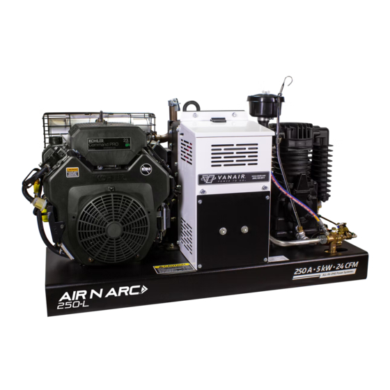
Vanair AIR N ARC RELIANT 250 Series Manuals
Manuals and User Guides for Vanair AIR N ARC RELIANT 250 Series. We have
1
Vanair AIR N ARC RELIANT 250 Series manual available for free PDF download: Operations Manual & Parts List
Vanair AIR N ARC RELIANT 250 Series Operations Manual & Parts List (184 pages)
All-in-One Power Systems
Brand:
Vanair
| Category:
Power Supply
| Size: 14.65 MB
Table of Contents
Warranty
7
Table of Contents
9
Table of Contents
10
Glossary
15
General Terms and Definitions
15
Welding Terms and Definitions
15
Air Compressor Terms and Definitions
16
Warranty Claims Procedure
19
Claims Process for Warranted Parts
19
Procedure
19
Introduction
23
Experience the Vanair Advantage
23
A Note on Manual Navigation
24
Section 1: Safety
25
General Information
25
Dangers, Warnings, Cautions, and Notes
25
International Safety Symbol
26
Arc Welding Hazards
26
Electrical Shock Can Kill
26
Fumes and Gases Can be Hazardsous
28
Build up of Gas Can Injure or Kill
28
Enclosed Spaces Can Cause Abuild-Up of Noxious Fumes and Overheating
29
Arc Rays Can Burn Eyes and Skin
29
Welding Can Cause Fire and Explosion
29
Flying Metal Can Injure Eyes
30
Hot Parts Can Cause Severe Burns
31
Noise Can Damage Hearing
31
Magnetic Fields Can Affect Pacemakers
31
Section 1: Safety (Continued)
31
Cylinders Can Explode if Damaged
31
Engine Hazards
32
Battery Explosion Can Blind
32
Fuel Can Cause Fire or Explosion
32
Moving Parts Can Cause Injury
33
Hot Parts Can Cause Severe Burns
33
Engine Exhaust Gases Can Kill
33
Enclosed Spaces Can Cause Abuild-Up of Noxious Fumes and Overheating
33
Battery Acid Can Burn Skin and Eyes
34
Engine Heat Can Cause Fire
34
Exhaust Sparks Can Cause Fire
34
Compressed Air Hazards
34
Breathing Ccompressed Air Can Cause Seriouis Injury or Death
34
Enclosed Spaces Can Cause Abuild-Up of Noxious Fumes and Overheating
34
Compressed Air Can Cause Injury
35
Trapped Air Pressure and Whipping Hoses Can Cause Injury
35
Hot Metal from Air Arc Cutting and Gouging Can Cause Fire or Explosion
35
Hot Parts Can Cause Severe Burns
35
Read Instructions
35
Additional Symbols for Installation, Operation and Maintenance
36
Falling Unit Can Cause Injury
36
Overheating Can Damage Motors
36
Flying Sparks Can Cause Injury
36
Overuse Can Cause Overheating
36
Enclosed Spaces Can Cause Abuild-Up of Noxious Fumes and Overheating
37
Tilting of Trailer Can Cause Injury
37
Read Instructions
37
Radiation Can Cause Interference
37
Arc Welding Can Cause Interference
38
California Proposition 65 Warnings
38
Principal Safety Standards
39
Emf Information
40
Safety Decals
40
Disposing of Machine Fluids
41
Section 2: Description
44
General Description
44
Compressed Air System
44
Compressor Unit
44
Air Intake / Air Filter
45
Pressure Relief Valve
46
Pilot Valve
46
Engine
47
Ac Generator
48
Instrumentation
49
Volts/Amps Display
51
Welder Function Switches
51
Fuel Gauge/Hour Meter
51
Engine Control (On/Off/Start) Switch
51
Circuit Breaker Overload Trip/Reset Buttons
51
Ac Voltage Outlets
52
Generator Control On/Off Toggle Switch
52
DC Charger Mode Toggle Switch
52
Volts/Amps Manual Adjustment Dial
52
Compressor Air Gauge
52
Battery Cable Receptacle
52
Welder Lead Connection
52
Section 3: Specifications
53
Section 4: Installation
57
Machine Package Receipt/Inspection
57
Machine Package Prep
57
Service Body Prep
57
Machine Package Mounting
58
Section 4: Installation (Continued)
58
Installation and Dimensions Diagram (Part 1 of 2)
61
Installation and Dimensions Diagram (Part 2 of 2)
62
Section 5: Operation
63
General Information
63
Engine Start-Up and Shutdown Procedure
65
Engine Start-Up
65
Engine Shutdown
66
Engine Throttle Control Functions
67
Operating the Welder
67
Welding Operator Procedure
68
CC (Constant Current) Mode
68
CV (Constant Voltage) Mode - Using a Voltage Sensing Suitcase Feeder
69
CV (Constant Voltage) Mode - Usinga Spool Gun
70
Operating the Generator
71
Operating the Air Compressor
71
Operating the Batter Booster/Charger
73
Connection - Disconnection Sequence and Operation
73
Extreme Condition Operation
74
Cold Weather Operation
75
Engine Operation
75
High Temperature Operation
75
High Altitude Operation
75
Section 6: Maintenance
77
General Information
77
Routine Maintenance Schedule
77
Maintenance Schedule Table
77
Replacement Parts
83
Parts Replacement and Adjustment Procedures
83
Compressor Air Filter
85
Compressor Air Filter Replacement
85
Compressor Oil Maintenance
87
Compressor Oil Change
88
Unloader Valve Maintenance
88
Section 6: Maintenance (Continued)
90
Low Pressure Valve Replacement
91
High Pressure Valve Maintenance
92
High Pressure Valve Replacement
93
Compressor Head Valve Assembly Inspection and Maintenance
94
Remove Valve Package
96
Assemble Valve Assembly Package
97
Assemble Valve Assembly Package into Compressor
98
Adjusting Compressor Cut-In/Cut-Out Pressure
98
Adjusting the Engine Speed
99
Replacing or Re-Tensioning the Compressor And/Or Generator Drive Belts
100
Accessing the Drive Belts - Removing the Belt Guard Shield
101
Replacing the Belt Guard Shield
102
Re-Tensioning the Air Compressor Drive Belt(S)
102
Compressor Belt Sizing
103
Compressor Belt Link Disengagement
104
Compressor Belt Assembly
105
Routing Compressor Belts Onto Pulley Grooves
106
Re-Tensioning or Replacing the Generator Serpentine Belt
107
Belt
107
Replacing the Generator Serpentine Drive Belt
109
Draining the Air Tank
111
Engine Maintenance
111
Engine Air Filter Maintenance
112
Checking the Engine Oil
113
Replacing the Engine Oil
115
Replacing the In-Line Fuel Filters
116
Engine Cooler Maintenance
117
Servicing the System Fuses and Circuit Breakers
118
Storage and Intermittent Use
120
Intermittent Use
120
Long Term Storage
120
Section 7: Troubleshooting
121
General Information
121
Section 7: Troubleshooting (Continued)
122
A Note on Condensation Due to Compression
122
Troubleshooting Guide
122
Section 8: Diagrams
133
General Information
133
Wiring Diagram - Air N Arc 200 Series
134
Wiring Diagram - Switches & Lights
135
Compressor Flow Schematic Diagram
136
Section 9: Illustrated Parts List
137
Parts Ordering Procedure
137
Air N Arc 200 Systems Assemblies
140
Compressor and Parts Assembly
142
Frame
144
Instrument Panel
146
Engine and Drive Parts
150
Belt Guard Assembly
152
Electrical System
154
Fuel Tank Assembly
158
Control Assembly
160
Decal and Plate Locations (1 of 3)
162
Decal and Plate Locations (2 of 3)
164
Decal and Plate Locations (3 of 3)
166
Appendix A: Additional Information
169
Electric Motor Chart - Starting Watts
169
Extension Cord Chart
170
Wattage Requirements for Common Receptacle Units
171
Air Tool Air Consumption Chart
172
Air N Arc 200 Series All-In-One Power System Available Options List
173
Hose Installation Guide
175
Electrode Ignition Procedure
176
Pressure System Control - Functional Sequences
177
Appendix B: Maintenance and Service Log
179
General Description
179
Maintenance and Service Log
180
Advertisement
Advertisement
Related Products
Vanair AIR N ARC RELIANT 300 Series
Vanair AIR N ARC RELIANT 150 Series
Vanair 282037
Vanair Start-All Jump-Pack 2500A
Vanair 050518
Vanair 050580
Vanair 050590
Vanair 050591
Vanair 050735
Vanair 050817
Vanair Categories
Power Supply
Welding System
Air Compressor
Remote Starter
Compressor
More Vanair Manuals
Login
Sign In
OR
Sign in with Facebook
Sign in with Google
Upload manual
Upload from disk
Upload from URL