
Related Manuals for SAMES KREMLIN FPro G


Summary of Contents for SAMES KREMLIN FPro G
- Page 1 FPro G II2G Ex h IIB T6 Gb X User manual 582166110 2021-03-11 Index A Original manual SAMES KREMLIN SAS 13 Ch emin de Malacher 38240 Meylan www.sames-kremlin.com 33 (0)4 76 41 60 60...
- Page 2 Any communication or reproduction of this document, in any form whatsoever, and any exploitation or communication of its contents are prohibited, unless expressly authorized in writing by SAMES KREMLIN. The descriptions and characteristics contained in this document are subject to change without prior notice.
-
Page 3: Table Of Contents
Initialization of the follow-up in production................39 Safety in production ......................... 39 Use of the FPro G ..........................39 Diagnostic Help / Troubleshooting Guide ..................40 Possible symptoms of faults - Causes of faults - Remedies to apply ....... 41... - Page 4 10.1 Preventive Maintenance Plan ....................42 10.1.1 Location of lubrication points - FPro G - FPro GSP ............43 10.2 Cleaning ............................. 45 10.3 Corrective maintenance......................45 10.4 Disassembly/Re-assembly operation ..................46 10.4.1 Dismantle the FPro G ....................... 46 10.4.2 Replace needle packing ....................
- Page 5 Evolution table Date Subject Revision FPro G 01 14 2021 Dear customer, you have just acquired your new equipment and we thank you for it. We have taken the greatest care, from design to manufacturing, to ensure that this equipment gives you complete satisfaction.
- Page 6 SAMES KREMLIN is limited to the replacement of the Material in its entirety or to the partial replacement of the defective component. SAMES KREMLIN will only bear the cost of the parts necessary to replace the defective Material.
- Page 7 Meanings of pictograms Danger: high Danger : general Explosive materials Danger: Electricity pressure signal (user) Toxic materials Corrosive materials Harmful or Danger : irritating materials pinching, crushing Risk of product Danger: hot rooms Danger: Danger: risk of emanation or surfaces automatic start, flammability moving parts...
- Page 8 Staff must have specific skills and experience in the technical field concerned. This applies in particular to maintenance and repair work on devices related to the FPro G gun. The personnel must be familiar with the standards, guidelines, accident prevention regulations and operating conditions in force.
-
Page 9: Safety Instructions
1 Safety instructions Life safety The equipment at your disposal is for professional use only. It must be used only for the purpose for which it was intended. Read the specified recommendations carefully: In the technical manuals of the equipment concerned. On device labels. - Page 10 In relation to the products and paints (liquid or powder) used with its equipment, SAMES KREMLIN cannot be held responsible for direct or indirect material damage caused in use, for the poor compatibility of...
- Page 11 Fire, explosion, arc, electricity The laws and regulations in force regarding safety, fire and electricity in the country where the equipment is used must be respected. The gun must be used in areas for which it has been validated. Refer to the ATEX section of the document.
- Page 12 These products must be stored in approved and grounded containers. Use only grounded metal pails for the use of rinsing solvents. Cardboard and paper are to be banned. Indeed they are very bad conductors, even insulators. The canisters of products and cleaners must be grounded, via the grounding cable, using clamps or any other means of attachment.
-
Page 13: Integrity Of The Material
Parts and accessories must be exclusively supplied or approved by SAMES KREMLIN. SAMES KREMLIN cannot be held responsible for personal injury as well as breakdowns and/or damage resulting from modification of the equipment. Any modification of the equipment made by the user and... - Page 14 Environment Environmental risks must be controlled as follows: Respect an average temperature of use of the equipment and products, which must be at least 5°C lower than the flash point of the products and within a range of 0 to 40°C. Ventilation of the area by forced extraction and supply of unpolluted air shall be mandatory during equipment operation or cleaning operations.
-
Page 15: Ue Declaration Of Conformity
SAMES nonché le normative nazionali e/o locali, de acordo com as preconizações de KREMLIN y a la normativa nacional y/o SAMES KREMLIN, bem como com outros • accertarvi utilizzatori local,... - Page 16 VYHLÁSENIE O ZHODE EU-MEGFELELŐSÉGI NYILATKOZAT DECLARAŢIA DE CONFORMITATE UE Le fabricant / The manufacturer / Der Hersteller SAMES KREMLIN SAS / El fabricante / Il produttore / O fabricante 13, chemin de Malacher / De fabrikant / Tillverkare / Valmistaja / Producent 38 240 - MEYLAN - FRANCE / Výrobce...
- Page 17 La présente déclaration de conformité est établie sous la seule responsabilité du fabricant / This declaration of conformity is issued under the sole responsibility of the manufacturer / Die alleinige Verantwortung für die Ausstellung dieser Konformitätserklärung trägt der Hersteller / La presente declaración de conformidad se expide bajo la exclusiva responsabilidad del fabricante / La presente dichiarazione di conformità...
-
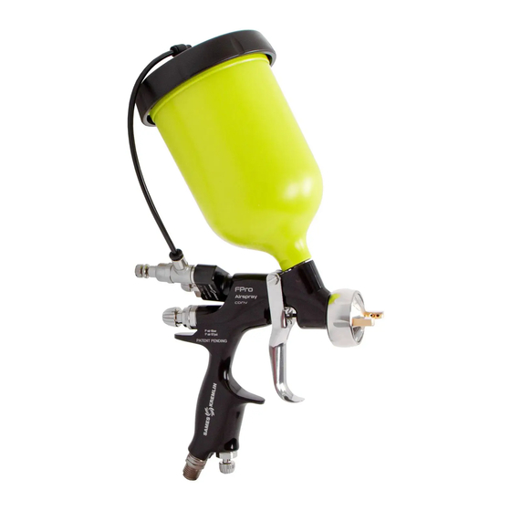
Page 18: Presentation Of Fpro G
3 Presentation of FPro G Usage Guns recommended spraying varnishes, lacquers, stains, polyurethanes. The product is fed by gravity via a compatible rigid or disposable cup. Refer to procedure: 12Disposable cups: smart cups... -
Page 19: Fpro G Gun Components
FPro G Gun Components Position Designation Position Designation Visual Visual Nozzle + needle Paint cup Vortex Air cap+ring Equipped nozzle GSP Kit (FPRO G GSP) -
Page 20: Dimensions Fprog - Fpro Gsp
Dimensions FPROG - FPRO GSP Figure 1 FPro G Figure 2 FPro G Figure 3 FPro GSP Figure 4 FPro GSP... - Page 21 Gun structure FPROG and FPRO GSP Adjustment of the KIT GSP Air valve Spray width product flow regulator adjustment Nozzle Seal packing Spray air cap Needle Trigger Adjustment of the Air supply compressed air flow rate...
-
Page 22: Equipment Identification
4 Equipment identification Material plan Principle of designation Referencing structure (below). HVLP FPro Gravity HVLP (High volume, Low pressure) LVLP Nozzle size (Low volume, Low pressure)( CONV : CONV CONVENTIONAL (Conventional) LP: HVLP and LVLP 12 : 1.2 mm 13 : 1.3 mm 14 : 1.4 mm 15 : 1.5 mm 18 : 1.8 mm... -
Page 23: Options
Coding principle: nozzle code and needle code CODE NOZZLE+TIP XX: nozzle Options Disposable cup - Smart Cup... -
Page 24: Versions Fpro G
With CUP With CUP With CUP Without CUP FPro G LVLP S/PROJ CUP FPro G LVLP 12-Mvb NO CUP FPro G CONV -12-Mvb NO CUP FPro G GSP CONV -15-Mvb CUP FPro G CONV S/PROJ CUP FPro G LVLP -12-Mvb CUP... -
Page 25: Standards Applied
Standards applied ATEX Directive 2014/34/EU. NF EN ISO 80079-36 June 2016 NF EN ISO 80079-37 June 2016 NF EN 1127-1 August 2019... -
Page 26: Description Of The Atex Marking
Refer requirements instruction manuals accompanying this product. Number given by SAMES KREMLIN. 20XX The first two digits indicate the year of manufacture. P air : 6 bar / 87 psi Max. air supply pressure of the gun P prod : 6 bar / 87 psi Max. -
Page 27: Visuals Of The Marking Elements
4.4.2 Visuals of the marking elements FPro G CONV FPro G LP FPro G GSP... -
Page 28: Technical Specifications And Performance
5 Technical specifications and performance Technical specifications FPro G CONV - FPro G CONV GSP FPro G CONV FPro G CONV GSP Type Gravity Maximum air supply pressure (network) 6 bar Maximum product feed pressure 1 bar Air flow rate... - Page 29 Materials FPro G Gun body Anodized polished forged aluminum Head Nickel-plated brass Nozzle INOX Needle INOX Gravity cup Plastic Air and Fluid connections Elements mounted on the gun (depending on model) and product supply Connection: M 1/4 NPS Ø 7 mm int. minimum (for a length of 7.5 assembly) M ¼...
- Page 30 Nozzle characterization principle Nozzle parameters Technology Nozzle size 12 : 1.2 mm • 13 : 1.3 mm • CONV (CONVENTIONAL) 14 : 1.4 mm • LP: HVLP and LVLP 15 : 1.5 mm • 18 : 1.8 mm • 22 : 2.2 mm •...
-
Page 31: Performances
1 bar. Principle of operation The FPro G is a pneumatic spray gun. A tool that ensures the projection and spraying of paint (or other liquid products: glue) only thanks to a compressed air supply in more or less large quantities, and under a pressure between 1 and 6 bars. -
Page 32: Installation
5 - Pneumatic gun The distance of 1 meter mentioned in this diagram is given only as an indication and could not engage the responsibility of SAMES KREMLIN. The exact delimitation of the areas is the express responsibility of the user, and this according to the products used, the environment of the equipment and the conditions of use. -
Page 33: Installation Diagram - Air Pressure Adjustment With Or Without Gauge At Gun Handle
Installation Diagram - Air Pressure Adjustment with or without Gauge at Gun Handle 1- Air pressure regulator and wall pressure gauge PO 2-Air hose 3 - Pressure measured at the gun grip during operation (air needle open) 4 - Gun FPro G... -
Page 34: Transport
Transport Put the product in its original packaging during transport. The packaging of the gun corresponds to the transport conditions provided for this purpose. The packaging protects: Damages related to transportation. Corrosion. Storage Our equipment must be stored in its original packaging. In case of prolonged storage, it is preferable to carry out preventive maintenance for all lubricants before commissioning. -
Page 35: Commissioning
Do not immerse the gun in solvents or aggressive products. Do not clean or immerse the GSP kit in solvents or aggressive media. Do not clean with wire brushes. Use only antistatic wipes for cleaning the equipment. Use only genuine SAMES KREMLIN spare parts and accessories. -
Page 36: Apply A Product On A Surface
Apply a product on a surface Select the right fitting for your installation Original equipment Option Connection ¼ Connection ¼ NPS (included in the accessories box) Connect the air hose. Check the proper operation of the gun without any product and make a pre-setting of the supply pressure. -
Page 37: User Settings
User settings See paragraph: 6.1General Installation Diagram . Product viscosity to use with the FPro G (without vortex) Technology HVLP LVLP CONV CONV GSP Nozzle size <20 s <20 s <20 s <20 s <20 s <20 s <20 s <20 s... -
Page 38: Ergonomic Gsp Position Adjustment For Right-Handed And Left-Handed Users
7.4.1 Ergonomic GSP position adjustment for right-handed and left-handed users For Left-Handed For Right-Handed The user of the FPRO GSP, left or right handed, can adapt and adjust the positioning of the GSP KIT for practical use at an angle of 180 degrees. -
Page 39: Initialization Of The Follow-Up In Production
1 bar max. in the GSP cup. Do not point the gun at yourself or anyone else while spraying Use an adapted and ATEX-certified conductive air hose. 8 Use of the FPro G First commissioning Refer to paragraph: 7 Commissioning... -
Page 40: Diagnostic Help / Troubleshooting Guide
9 Diagnostic Help / Troubleshooting Guide Visual Topic Explanation The defect comes from the head: loosen the ring slightly and rotate the head half a turn. If the defect is reversed, one of the side vents is blocked or deformed. Bean-shaped Then clean the gun head with solvent and unclog the spray... -
Page 41: Possible Symptoms Of Faults - Causes Of Faults - Remedies To Apply
Possible symptoms of faults - Causes of faults - Remedies to apply Defaults Root causes Remedies • Paint no longer comes out of • Nozzle partially or completely • Disassemble and clean the the gun clogged nozzle with solvent and a smooth brush •... -
Page 42: Maintenance
10 Maintenance 10.1 Preventive Maintenance Plan Maintenance plan Equipment Operation Reference elements Type of Condition of the necessary for Intervening staff maintenance equipment maintenance Sub-assembly Element Wording Periodicity (range, manual, QR Code) Visual inspection of the installation. Check for leaks. Check General installation General OPER... -
Page 43: Location Of Lubrication Points - Fpro G - Fpro Gsp
10.1.1 Location of lubrication points - FPro G - FPro GSP FPro G 560440001 : PTFE grease 450 GR. Box 560440101 : 10 ML GREASE PTFE CARTRIDGE... - Page 44 Location of lubrication points - FPro G - FPro GSP (continued) FPro G GSP 560440001 : PTFE grease 450 GR. box 560440101 : 10 ML GREASE PTFE CARTRIDGE...
-
Page 45: Cleaning
10.2 Cleaning Clean gravity cup The gravity cup is made of special antistatic materials. Do not create electrostatic charges by friction. Use only a damp cloth or antistatic wipes if manual cleaning is required in a hazardous area. 10.3 Corrective maintenance Replace hoses if worn. -
Page 46: Disassembly/Re-Assembly Operation
10.4 Disassembly/Re-assembly operation 10.4.1 Dismantle the FPro G Unscrew the projector Objectives Procedure to be carried out within the framework of maintenance. Reminder: Assembly errors The use of improper replacement or defective parts may result in hazards to personnel, damage, malfunction or general shutdown of the equipment. - Page 47 Step 1 Unscrew the complete head and remove it Step 2 Remove: The ring seal (A). The friction seal (B) The bare head (C). The retaining ring (D). The head ring seal (E). Step 3 Pull the trigger.
- Page 48 Step 4 Unscrew the nozzle equipped with the wrench supplied with the gun. Step 5 Remove the distribution ring (1) and the nozzle seal (2).
- Page 49 Step 6 Remove the vortex (1) and distribution ring (2). Observe the alignment of the ring position along the axis of the figure below for reassembly.
- Page 50 Step7 Loosen the nut. Step 8 Unscrew and remove the needle stop. Step 9 Remove the needle spring and the needle from the back of the gun.
-
Page 51: Replace Needle Packing
10.4.2 Replace needle packing Objectives Procedure to be carried out within the framework of maintenance. Ensure tightness between the needle and the body of the gun. Intervening staff Qualified personnel. Step 1 Check that there is no more product in the cup and in the gun. Rinse the gun and the cup. - Page 52 Step 3 Remove the trigger by removing the screw and trigger pin with two 5.5 wrenches. Step 4 Unscrew the liner press using the key supplied with the gun. Step 5 Pull out the needle packing which consists of a seat and a bearing.
- Page 53 Step 6 Reassemble the new filling. Insert the bearing into the seat and place the new assembly into the gun. Step 7 Screw on the packing press loosely. Step 8 Grease the needle. 560440001 : PTFE grease 450 GR. box 560440101 : 10 ML GREASE PTFE CARTRIDGE Step 9 Reassemble the needle.
- Page 54 Step 10 Reassemble the needle spring and the needle stop. Step 11 Tighten the nut. Step 12 Fully tighten the liner press with the key supplied with the gun and unscrew by a quarter turn. Note: If leakage is present, tighten slightly at the packing press.
- Page 55 Step 13 Raising the trigger Step 14 Feed in air and product.
-
Page 56: Replace Air Valve
10.4.3 Replace air valve Step 1 Loosen the nut. - Page 57 Step 2 Unscrew the needle stop, then remove the needle spring and needle from the back of the gun.
- Page 58 Step 3 Activate the trigger and unscrew the liner with the key supplied with the gun. Step 4 Squeeze the trigger to move the valve.
- Page 59 Step 5 Extract: The valve spring, The air valve, The liner. Step 6 Reassemble the liner on the new air valve. Step 7 Reassemble the liner on the new air valve. Grease the valve seals. 560440001 : PTFE grease 450 GR. box 560440101 : 10 ML GREASE PTFE CARTRIDGE Step 8 Put the liner in place.
- Page 60 Step 9 Back up: The greased needle, The needle spring, The needle stop. Tighten the nut.
-
Page 61: Replace Air Valve Seal
10.4.4 Replace air valve seal Step 1 Remove the air valve - see previous paragraph. Step 2 Remove the seal. Grease the new seal and place it in its housing. 560440001 : PTFE grease 450 GR. box 560440101 : 10 ML GREASE PTFE CARTRIDGE Important For reassembly, carefully insert the air valve into the gun body with a rotating movement so as to preform the valve seal. -
Page 62: Replace The Air Needle At Events And The Air Needle At The Grip
10.4.5 Replace the air needle at events and the air needle at the grip. Step 1 Unscrew the air needle at the vents and/or the air needle at the grip using the key supplied with the gun. The air needle must be in the "open" position before being mounted or dismounted from the gun. - Page 63 Step 2 Check the condition of the clip and change it if necessary. Step 3 Refit the new air needle to the air vents and/or the air needle to the stock - tightening torque: 10 Nm.
-
Page 64: Replace The Gsp Kit
10.4.6 Replace the GSP kit Objectives Procedure to be carried out within the framework of maintenance. Intervening staff Qualified personnel. Prerequisite The GSP regulator kit must not be cleaned with solvents or immersed in solvents. Do not pull the trigger and open the cup lid at the same time. Maximum allowable pressure in the GSP cup: 1 bar / 14 psi. - Page 65 Step 1 To remove the hose, apply pressure from top to bottom on the arrowed element.
- Page 66 Step 2 Loosen the regulator. Step 3 Unscrew the air needle using the key supplied with the gun.
- Page 67 Step 4 Remove the ring and air needle assembly. Step 5 Separate the ring from the needle. Step 6 Remove both seals from the ring.
- Page 68 Step 7 Check that there are no deposits or residues in the ring chamber. Blow a blower if necessary. Grease the new seals and place them inside the ring. 560440001 : PTFE grease 450 GR. box 560440101 : 10 ML GREASE PTFE CARTRIDGE Check the correct arrangement of the seals in the ring chamber.
- Page 69 Step 10 Remove the seal from the liner. Use a flat screwdriver. NOTE: Be careful not to scratch the liner or damage the seal groove. Possible residues or seal deposits caused by the removal of the seal with the screwdriver. Step 11 Check that there are no deposits or residues in the liner.
- Page 70 Step 12 Reassemble the GSP kit using the reverse procedure to that described in the previous steps of this procedure. Check that the liner threads are properly engaged in the gun before tightening the liner with a wrench.
-
Page 71: Replace The Air Connection
Adapt the air inlet fitting of the gun to the hose in place. Intervening staff Qualified personnel. Step 1 Unscrew the air connection from the gun body using the wrench supplied with the FPro G gun. Step 2 Install the new air connection instead. -
Page 72: Replace The Gravity Cup
10.4.8 Replace the gravity cup Objectives Procedure to be carried out within the framework of maintenance. Intervening staff Replace a damaged cup or replace it by a disposable cup Prerequisite Check that the cup is empty. - Page 73 Step 1 Unscrew the lid with the cup. The cup is unscrewed by hand. If resistance is encountered, unscrew the gravity cup at the connection using the wrench supplied with the gun. Step 2 Extract the anti-drip membrane...
- Page 74 Step 3 Install the new anti-drip membrane. Step 4 Screw on the gravity cup by hand.
-
Page 75: Replace Of Defective Parts
10.5 Replace of defective parts After complete shutdown equipment, preventive maintenance can be performed according to the recommendations in the manual and using original SAMES KREMLIN spare parts or approved consumables. -
Page 76: Disposable Cups: Smart Cups
11 Disposable cups: smart cups Disposable or single-use cups are an alternative to the conventional gravity cup. These cups are composed of a flexible pouch, a lid with filter, a holding ring and a cap. Refer to 11.9 Consumable references 11.1 Assembly instructions Step 1 Thread adapter to spray gun. - Page 77 Step 4 Pour the paint inside the liner. Be careful not to spill the paint on to the flange/ring. Step 5 Mix the paint with a stir stick. Ensure that the paint has not coated the flange/ring before attaching the lid Step 6 Seat lid into ring.
- Page 78 Step 8 Press the clamps on the lid down to secure It to the dosing cup. Step 9 Connect the cup assembly to the spray gun, perforating the membrane on the lid. Step 10 Press the clamps on the lid to secure the Lid to the adapter.
-
Page 79: Storage Instructions
11.2 Storage instructions Step 1 Turn the paint gun upside down, cup down, without air pressure, and pull the trigger to purge the gun paint remaining (in the paint gun will flow into the disposable cup) Step 2 Push the tabs down to release adaptor locks Step 3 Remove the gun with the adapter. - Page 80 Step 4 Put the cap on the lid of the liner. Step 5 Unclip the tabs from the dosing cup. Step 6 Remove the liner from the dosing cup.
-
Page 81: Disposal Instructions
Step 7 Remove the cap and puge air by carefully compressing the liner while the opening is upwards. Check that the paint permeates the filter. Step 8 Put the cap on and store. 11.3 Disposal instructions Repeat steps 1 to 6, then remove the liner. No need to purge air before disposing of the liner NOTE: Dispose in conformance with local rules and regulations. -
Page 82: Spare Parts
136790318 FPro G LVLP 18-Mvb CUP 136790322 FPro G LVLP 22-Mvb CUP FPro G LP without cup 135790312 FPro G LVLP 12-Mvb NO CUP 135790313 FPro G LVLP 13-Mvb NO CUP 135790314 FPro G LVLP 14-Mvb NO CUP 135790315 FPro G LVLP15-Mvb NO CUP... - Page 83 136794318 FPro G CONV -18-Mvb CUP 136794322 FPro G CONV -22-Mvb CUP FPro G CONV without cup 135794312 FPro G CONV -12-Mvb NO CUP 135794313 FPro G CONV -13-Mvb NO CUP 135790314 FPro G CONV 14-Mvb NO CUP 135790315 FPro G CONV 15-Mvb NO CUP...
-
Page 84: Exploded View Of The Fpro G Gun
12.2 Exploded view of the FPro G gun Section A Designations Air cap ring Friction seal Air cap Retaining ring Air cap ring’s o-ring seal Distribution washer Nozzle Nozzle’s o-ring seal Distribution ring Vortex Section Section B Designations Cup connection... - Page 85 Exploded view of the FPro G gun (continued) Section C Designations Steel Circlip PTFE Seal Needle sleeve Short air needle Valve actuator One-piece valve body Valve seal x2 Valve seal HDPE 300 Air valve spring FPro G Rear liner Needle...
-
Page 86: Exploded View Of The Fpro Gsp Gun
Air cap ring’s o-ring seal Nozzle Buse Nozzle’s o-ring seal Distribution ring Vortex Section Section B Designations Cup connection Gun body FPro G GSP Packing holder Teflon bearing Seat Trigger axle Stainless steel screw H M4X8 Trigger Circlip O-ring PTFE Needle liner Short air needle Connection M R1/4 M ¼... - Page 87 Section C Designations Steel circlip PTFE Seal Valve actuator One-piece valve body Valve seal x2 Valve seal HDPE 300 Air valve spring FPro G Sleeve Needle Needle spring FPro G Locking nut M12x100 Magnetic needle stop Cup body Filter Anti-drip membrane 0.6L Cup seal...
-
Page 88: Consumable References
1-2-3-4-5 132790200 FPro G head HVLP-12 22-Lvb 129130004 Pack of 5 distribution washer 6-7-8-31 131799912 TIP + NEEDLE 12 - FPRO G 6-7-8-31 131799913 TIP + NEEDLE 13 - FPRO G 6-7-8-31 131799914 TIP + NEEDLE 14 - FPRO G... - Page 89 Rear line assembly FPro G 029030003 Sleeve 133790300 Needle tip 22-27 & needle magnetic support 07-40 FPro G 133790400 Needle tip 07-13 & needle magnetic support 07-40 FPro G 133790500 Needle tip 14-18 & needle magnetic support 07-40 FPro G...
- Page 90 138790114 Starter Kit Smart Cups - 12 units - 750 mL - filter 125 µm 12 cups +1 dosing cup +1 adaptor FPRO G + 1 stir stick 138790115 Starter Kit Smart Cups - 12 units - 750 mL - filter 190 µm...
-
Page 91: Wear Part References
Pack of 10 air valve seals 19-20- 129798901 Pack of seals GSP kit 37-39-45 139270005 Filter 139790105 Pack of 5 anti drip diaphgrams FPro G Level 1 preventive maintenance * Level 2 Corrective Maintenance ** Level 3 Exceptional Maintenance ***... -
Page 92: References For Spare Parts Or Repair Kits
12.6 References for spare parts or repair kits Level of maintenance Positions References Designations Visuals Quantity spare parts 19-20-42-43-44-45- 129798100 Kit GSP without cup - FPro GSP 19-20-35-36-37-39- 40-41-42-43-44-45- 139798200 Kit GSP with cup - FPro GSP 46-47 049221800 Gravity gun table bracket 049221900 Gravity gun wall bracket Level 1 preventive maintenance *...
Need help?
Do you have a question about the FPro G and is the answer not in the manual?
Questions and answers