Table of Contents
Advertisement
Quick Links
Advertisement
Table of Contents

Related Manuals for Circutor GETEST MPC-5


Summary of Contents for Circutor GETEST MPC-5
- Page 1 Step and contact voltage meter GETEST INSTRUCTIONS MANUAL (M98224701-03-20A)
- Page 2 GETEST Instructions Manual...
-
Page 3: Safety Precautions
CIRCUTOR, SA reserves the right to make modifications to the device or the unit specifications set out in this instruction manual without prior notice. CIRCUTOR, SA on its web site, supplies its customers with the latest versions of the device specifica- tions and the most updated manuals. -
Page 4: Table Of Contents
GETEST CONTENTS SAFETY PRECAUTIONS ���������������������������������������������������������������������������������������������������������������������������������������������������������3 DISCLAIMER ��������������������������������������������������������������������������������������������������������������������������������������������������������������������������3 CONTENTS �����������������������������������������������������������������������������������������������������������������������������������������������������������������������������4 REVISION LOG �����������������������������������������������������������������������������������������������������������������������������������������������������������������������5 SYMBOLS �������������������������������������������������������������������������������������������������������������������������������������������������������������������������������5 1�- VERIFICATION UPON RECEPTION ������������������������������������������������������������������������������������������������������������������������������������6 1�1�- RECEPTION PROTOCOL ���������������������������������������������������������������������������������������������������������������������������������������������6 1�2�- TRANSPORTATION AND HANDLING �������������������������������������������������������������������������������������������������������������������������6 1�3�- STORAGE ������������������������������������������������������������������������������������������������������������������������������������������������������������������ 7 2�- PRODUCT DESCRIPTION �������������������������������������������������������������������������������������������������������������������������������������������������8 3�- DEVICE INSTALLATION ����������������������������������������������������������������������������������������������������������������������������������������������������9 3�1�- PRELIMINARY RECOMMENDATIONS ������������������������������������������������������������������������������������������������������������������������9 3�2�- INSTALLATION �������������������������������������������������������������������������������������������������������������������������������������������������������... -
Page 5: Revision Log
GETEST REVISION LOG Table 1: Revision log� Date Revision Description 01/20 M98224701-03-20A Comprehensive revision of the manual SYMBOLS Table 2: Symbols Symbol Description In accordance with the relevant European directive. In accordance with the direct CMiM. In accordance with the direct UKCA (UK Conformity Assessed) Device compliant with European Directive 2012/19/EC. -
Page 6: 1�- Verification Upon Reception
- Cable for connecting the measuring electrodes - Measurement spikes - 2 keys - Instruction manual If you notice any reception issue, immediately contact the carrier and/or CIRCUTOR after-sales service. 1�2�- TRANSPORTATION AND HANDLING Transportation, loading and unloading and handling of the device must be carried out with the appropriate precautions and manual or mechanical tools to avoid de- terioration. -
Page 7: 1�3�- Storage
GETEST The centre of gravity of some device may be at a considerable height. Therefore, when it is handled by forklifts, it is advisable to hold the device properly and not make sudden manoeuvres. It is advisable not to suspend the device at a height greater than 20 cm from the ground. To unload and move the device, a forklift with shovels must be used, which should cover the entire depth of the base. -
Page 8: 2�- Product Description
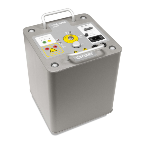
GETEST 2.- PRODUCT DESCRIPTION GETEST is an device that measures the step and contact voltages that can appear in transformation centres, substations and high voltage lines. To carry out the measurements, the device injects current during a mains cycle (20 ms), providing up to 50 A for a maximum earth resistance of 10 Ω. -
Page 9: 3�- Device Installation
GETEST 3.- DEVICE INSTALLATION 3�1�- PRELIMINARY RECOMMENDATIONS The installation, operation and maintenance of LV device must only be carried out by authorised installers. The complementary technical instruction ITC-BT-03 develops the provisions of article 22 of the Low Voltage Electrotechnical Regulation, establishing the conditions and requirements that must be observed for the certification of the competence and the corresponding administrative authorisation of the approved installers in the application field for Low Voltage Electrotechnical... -
Page 10: 3�2�- Installation
GETEST 3�2�- INSTALLATION The GETEST can be powered directly from the mains (230 V~ and 50 Hz) or from a single-phase generator set. The required power of the generator set will come as a function of the value of the loop resistance of the circuit. - Page 11 GETEST 3�3�- GTEST Probe: MEASUREMENT ELECTRODE The GTEST Probe measurement electrode is an accessory that simplifies feed-through and contact voltage measurements by replacing the 25 kg weights. The measurement electrodes allow a person to use their weight to make the measurement. Because the GETEST device can generate up to 600 V~, the measurement electrode is properly insulated.
-
Page 12: 4�- Operation
GETEST 4.- OPERATION 4�1�- DESCRIPTION OF THE DEVICE Safety key LED Power Main switch Voltage terminals Power supply Current injection connector terminals Resistance switch LED Link Figure 3: Device description� Table 4: GETEST LEDs� Description POWER Indicates that the device is powered. Indicates that the device has been wirelessly connected to the LINK Getest application on the Smartphone. -
Page 13: 4�2�- Description Of The Getest App
GETEST 4�2�- DESCRIPTION OF THE Getest APP The Getest application consists of 2 screens: a Control screen to programme the device and another screen for Results. A description of the control screen is shown in Figure 4 Results screen Control screen Wireless connection Device Identifier button... - Page 14 GETEST CIRCUTOR SA - Vial Sant Jordi, s/n 08232 Viladecavalls (Barcelona) Spain MPC 5-50/Getest 0...40ºC Main Module S/N IP20-Class I CAT II-300V 230±20%Vac Bluetooth S/N 50/60Hz 30kW/20ms Date Made in EU (Spain) Figure 5: Getest label� 5�- Once the device is linked, open the Getest application.
- Page 15 �������� = �������� ���������������� �������� . �������� �������� �������� �������� �������� �������� �������� �������� �������� �������� �������� �������� × �������� �������� GETEST ���������������� �������� . �������� �������� �������� �������� �������� �������� �������� �������� = ���������������� �������� . �������� �������� �������� �������� �������� �������� �������� ��������...
- Page 16 GETEST The thermo-magnetic switch and the safety key are independent devices, and act directly on the mains supply (switch) or on the output current (safety key). In this way, even in the unlikely failure of software / hardware, these two devices allow to avoid the current injection. 11�- Once the test is completed, on the Results screen of the application, all the results can be consulted Figure 6...
-
Page 17: 4�4�- Test Types
GETEST 4�4�- TEST TYPES 4�4�1�- CONNECTION OF THE HARDWARE GROUND AND AUXILIARY GROUND Connect one of the current injection terminals of the GETEST (Ip) to the hardware or protection ground of the transformation centre or substation. Do not confuse the hardware ground fittings with the service ground, even though in some grounding systems these are interconnected. -
Page 18: 4�4�2�- Step Voltage
GETEST Regardless of the type of test, the auxiliary ground must suffice to allow for correct measurements to be taken. A bad auxiliary ground adds series resistance to the circuit, which reduces the performance of the device, thereby limiting the capacity to inject current. If you try to take the measurements with a high auxiliary ground, an Error message appears on the application screen, warning of this situation. - Page 19 GETEST Access door Measuring Auxiliary ground electrodes Hardware ground ≥ 40 m Figure 11: Step voltage Test connection� The recommended distance between the hardware ground fitting and the auxiliary ground is 5 times the diagonal of the substation enclosure or the transformation centre.
-
Page 20: 4�4�3�- Contact Voltage
GETEST Keep an upright and relaxed position while standing on the electrodes. For a correct measurement, the weight of the person must be at least 50 kg. 7�- Once the connections have been made, commence the test, please refer to “ ”�... - Page 21 GETEST Access door Measuring Auxiliary ground electrodes Hardware ground ≥ 40 m Figure 14: Contact voltage Test connection� 4�- Ensure the electrodes are stable. Despite featuring a non-slip design, the electrodes can slide on the surface. Make sure they are stable before using them. 5�- Stand on the electrodes, stepping inside the marked surface, Figure 15 Figure 15: Stand on the electrodes�...
-
Page 22: 4�4�4�- Ground Resistance
GETEST 7�- Once the connections have been made, commence the test, please refer to “ ”� 4.3. START-UP Measurements must be carried out respecting at all times the diagrams and warnings outlined in this manual. Otherwise the obtained values might be erroneous. Do not touch the metal surfaces during the measurements. -
Page 23: 4�5�- Warning And Error Messages
GETEST Measurements must be carried out respecting at all times the diagrams and warnings outlined in this manual. Otherwise the obtained values might be erroneous. Pouring water around the auxiliary land (spikes system) or increasing the number of spikes are measures that can solve the problem. 4�5�- WARNING AND ERROR MESSAGES Table 6 shows the warning and error messages that may occur during the test. - Page 24 GETEST Table 6 (Continued): Warning and error messages Message Cause Solution Error: Unable reach required current, there is a GETEST being asked to supply more drop in the device's supply power than the electricity grid is capable of voltage� The installation to supplying.
-
Page 25: 5�- Technical Features
GETEST 5.- TECHNICAL FEATURES 5�1�- GETEST AC Power supply Rated voltage 230 V ~ ± 20% (L1-N) Frequency 50 ... 60 Hz Current 15 A ~ Installation category CAT II 300 V Measurement circuit Maximum output voltage 600 V ~ Maximum current 50 A at 10 Ω... - Page 26 GETEST (Continued) Environmental features Protection degree IP20 Mechanical features Terminal Power Supply IEC320 C20 16A Injection Current 4 mm safety banana CAT IV 600 V 32 A Voltage measurement 4 mm safety banana CAT IV 600 V 32 A Dimensions Figure 17 Weight 45 kg (Electrodes not included)
- Page 27 GETEST 5�2�- GETEST Probe Environmental features Operating temperature 5 ºC ... 40 ºC Storage temperature 5 ºC ... 40 ºC Maximum Altitude 2000 m Installation category CAT II 600 V PD3 Mechanical features Connection Banana type 4 mm Figure 18 Dimensions Packaging 690 x 210 x 85 mm...
-
Page 28: 6�- Maintenance And Technical Service
GETEST 6.- MAINTENANCE AND TECHNICAL SERVICE In the case of any query in relation to device operation or malfunction, please contact the CIRCUTOR, SA Technical Support Service. Technical Assistance Service Vial Sant Jordi, s/n, 08232 - Viladecavalls (Barcelona) Tel: 902 449 459 ( España) / +34 937 452 919 (outside of Spain) email: sat@circutor.com... -
Page 29: 8�- Ce Certificate
GETEST 8.- CE CERTIFICATE Instructions Manual... - Page 30 GETEST Instructions Manual...
- Page 31 GETEST Instructions Manual...
- Page 32 CIRCUTOR, SA Vial Sant Jordi, s/n 08232 - Viladecavalls (Barcelona) Phone:(+34) 93 745 29 00 - Fax:(+34) 93 745 29 14 www.circutor.es central@circutor.es...
Need help?
Do you have a question about the GETEST MPC-5 and is the answer not in the manual?
Questions and answers