Table of Contents
Advertisement
Quick Links
Advertisement
Table of Contents

Subscribe to Our Youtube Channel
Related Manuals for Circutor CVM-D41 DC


Summary of Contents for Circutor CVM-D41 DC
- Page 1 Power analyzer CVM-D41 DC INSTRUCTION MANUAL (M337B01-03-22A)
- Page 2 CVM-D41 DC Instruction Manual...
-
Page 3: Safety Precautions
CIRCUTOR S�A�U� reserves the right to make modifications to the device or the unit specifications set out in this instruction manual without prior notice. CIRCUTOR S�A�U� on its web site, supplies its customers with the latest versions of the device specifi- cations and the most updated manuals. -
Page 4: Table Of Contents
CVM-D41 DC CONTENTS SAFETY PRECAUTIONS ���������������������������������������������������������������������������������������������������������������������������������������������������������3 DISCLAIMER ��������������������������������������������������������������������������������������������������������������������������������������������������������������������������3 CONTENTS �����������������������������������������������������������������������������������������������������������������������������������������������������������������������������4 REVISION LOG �����������������������������������������������������������������������������������������������������������������������������������������������������������������������6 SYMBOLS �������������������������������������������������������������������������������������������������������������������������������������������������������������������������������6 1�- VERIFICATION UPON RECEPTION ������������������������������������������������������������������������������������������������������������������������������������7 2�- PRODUCT DESCRIPTION �������������������������������������������������������������������������������������������������������������������������������������������������7 3�- DEVICE INSTALLATION ��������������������������������������������������������������������������������������������������������������������������������������������������� 8 3�1�- PRIOR RECOMMENDATIONS ����������������������������������������������������������������������������������������������������������������������������������� 8 3�2�- INSTALLATION ������������������������������������������������������������������������������������������������������������������������������������������������������� 8 3�3�- DEVICE TERMINALS �������������������������������������������������������������������������������������������������������������������������������������������������9 3�4�- CONNECTION DIAGRAM �����������������������������������������������������������������������������������������������������������������������������������������10... - Page 5 CVM-D41 DC 5�6�3�- BACKLIGHT OF THE DISPLAY ������������������������������������������������������������������������������������������������������������������������ 38 5�6�4�- LIGHT ALARM �������������������������������������������������������������������������������������������������������������������������������������������������39 5�6�5�-DISPLAY HOME SCREEN����������������������������������������������������������������������������������������������������������������������������������39 5�6�6�- REFRESH TIME ���������������������������������������������������������������������������������������������������������������������������������������������� 40 5�6�7�- DELETING THE MAXIMUM & MINIMUM VALUES �������������������������������������������������������������������������������������������� 40 5�6�8�- DELETING THE ELECTRICAL CHARGE TOTALISERS ���������������������������������������������������������������������������������������� 41 5�6�9�- DELETING THE ENERGY TOTALISERS �������������������������������������������������������������������������������������������������������������� 41 5�6�10�- SAVE CONFIGURATION ���������������������������������������������������������������������������������������������������������������������������������42...
-
Page 6: Revision Log
CVM-D41 DC REVISION LOG Table 1: Revision log� Date Revision Description 04/22 M337B01-03-21A Initial version Changes in the following sections: 09/22 M337B01-03-22A 3.4. - 5.1. - 5.1.5. - 6.3.6.1. - Annex A SYMBOLS Table 2: Symbols� Symbol Description In compliance with the relevant European directive. -
Page 7: 1�- Verification Upon Reception
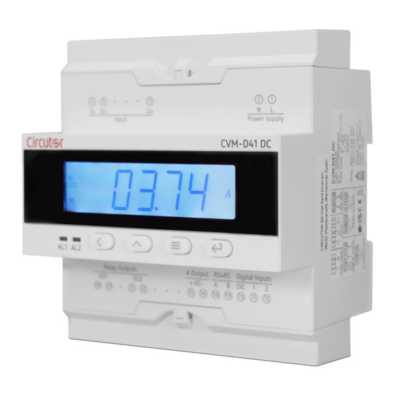
If any problem is noticed upon reception, immediately contact the transport com- pany and/or CIRCUTOR’s after-sales service. 2.- PRODUCT DESCRIPTION The CVM-D41 DC is designed to measure and display the DC volt age, DC current, power, energy electric charge. The device features: - 4 keys that allow you to browse between the various screens and program the device. -
Page 8: 3�- Device Installation
The CVM-D41 DC device must be installed by authorised and qualified staff. The power supply plug must be disconnected and measuring systems switched off before handling, al- tering the connections or replacing the device. -
Page 9: 3�3�- Device Terminals
CVM-D41 DC 3�3�- DEVICE TERMINALS Figure 1: CVM-D41 DC terminals (Upper)� Table 4: CVM-D41 DC terminals (Upper)� Device terminals 5: IU-, Current measurement input / 1: L, Power supply Voltage measurement input 2: N, Power supply 4: I +, Current measurement input... -
Page 10: 3�4�- Connection Diagram
CVM-D41 DC 3�4�- CONNECTION DIAGRAM 3�4�1�- VOLTAGE AND CURRENT MEASUREMENT WITH SHUNT AT THE NEGATIVE POLE OF THE IN- STALLATION Alimentación Auxiliar Carga Shunt Power Supply Load 31 32 70 71 72 RS-485 Salida de relés Salida Analógica Relay output... -
Page 11: 3�4�1�- Voltage And Current Measurement With Shunt At The Negative Pole Of The Installation
CVM-D41 DC 3�4�2�- VOLTAGE AND CURRENT MEASUREMENT WITH SHUNT AT THE POSITIVE POLE OF THE IN- STALLATION Shunt Alimentación Auxiliar Carga Power Supply Load 31 32 70 71 72 RS-485 Salida de relés Salida Analógica Relay output Analog output DIC 1 2... -
Page 12: 3�4�3�- Voltage Measurement
CVM-D41 DC 3�4�3�- VOLTAGE MEASUREMENT Alimentación Auxiliar Carga Power Supply Load 31 32 70 71 72 RS-485 Salida de relés Salida Analógica Relay output Analog output DIC 1 2 Entradas Digitales Digital inputs Figure 5: Voltage measurement� Note: To keep noise from appearing on the current screen, we recommend installing a jumper between terminals 4 and 5. -
Page 13: 3�4�4�- Current Measurement With Shunt At The Negative Pole Of The Installation
CVM-D41 DC 3�4�4�- CURRENT MEASUREMENT WITH SHUNT AT THE NEGATIVE POLE OF THE INSTALLATION Alimentación Auxiliar Carga Shunt Power Supply Load 31 32 70 71 72 RS-485 Salida de relés Salida Analógica Relay output Analog output DIC 1 2 Entradas Digitales Digital inputs Figure 6: Current measurement (shunt negative pole)�... -
Page 14: 3�4�5�- Current Measurement With Shunt At The Positive Pole Of The Installation
CVM-D41 DC 3�4�5�- CURRENT MEASUREMENT WITH SHUNT AT THE POSITIVE POLE OF THE INSTALLATION Shunt Alimentación Auxiliar Carga Power Supply Load 31 32 70 71 72 RS-485 Salida de relés Salida Analógica Relay output Analog output DIC 1 2 Entradas Digitales Digital inputs Figure 7: Current measurement (shunt positive pole)�... -
Page 15: 4�- Operation
The status of the digital inputs, if an input is connected, its corresponding number flashes. The status of the relay outputs, if a relay is closed, its corresponding number flashes. 4�2�- KEYBOARD FUNCTIONS The CVM-D41 DC features 4 keys to display and configure the device, Figure 9 Table 6... -
Page 16: 4�3�- Leds
CVM-D41 DC Table 6 (Continuation): Keyboard functions� Keystroke Long keystroke (> 3s): Enter in configuration menu In the configuration menu: Jump to the next level / Confirm an operation Alimentación Auxiliar Carga Shunt Power Supply Load 4�3�- LEDs The device has 2 LEDs, AL1 and AL2 (... -
Page 17: 4�5�- Analog Output
Figure 10 vated depending on the value of the digital inputs (See “5.4.- RELAY OUTPUT 1” and “5.5.- RELAY OUTPUT 2”) 4�7�- DISPLAY The CVM-D41 DC features 7 display screens, . Use keys to browse through the Table 8 different screens. -
Page 18: 4�7�1�- Maximum & Minimum Values
CVM-D41 DC Table 8: (Continued): Display menu� Display menu 28347 k W h Positive energy 03607 k W h Negative energy 00047 Positive electric charge 00007 Negative electric charge The home screen, meaning the first screen displayed when powering up the device or when exiting the "�... -
Page 19: 4�7�2�- Totalisers
CVM-D41 DC 4�7�2�- TOTALISERS For the Positive Energy, Negative Energy, Positive Electric Charge and Negative Electric Charge pa- rameters, the value of Energy or Electric Charge since the device was started can be viewed by pressing the key while the corresponding parameter is being displayed. -
Page 20: 5�- Configuration
Con guration of the display Software version Figure 11: CVM-D41 DC configuration menu� From any screen of the configuration menus, if no key is pressed for 4 minutes, the device leaves the configuration menu and returns to the display screen. - Page 21 CVM-D41 DC , key to access the configuration menu in the display mode, i.e., On the screen, press the the configuration parameters cannot be modified. On the screen, press the keys to access the configuration menu in the program- ming mode, i.e., the configuration parameters can be modified.
-
Page 22: 5�1�- Configuration Of The Input
CVM-D41 DC 5�1�- CONFIGURATION OF THE INPUT shows the main screen of the input configuration menu, where the input measurement range Figure 14 and the display value are configured. inPt Figure 14: Input configuration menu, main screen� Press the key to open the configuration menu. -
Page 23: 5�1�1�- Voltage Display Value
CVM-D41 DC 5�1�1�- VOLTAGE DISPLAY VALUE This screen is used to configure the voltage value to display when the maximum value of the voltage measurement range is input to the device. Pt-1 1000 Use the , key to modify the value of the flashing digit When the desired value is shown on the screen, press the key to skip the digit. -
Page 24: 5�1�3�- Current Display Value
CVM-D41 DC 5�1�3�- CURRENT DISPLAY VALUE This screen is used to configure the current value to display when the maximum value of the current is input to the device. Ct-1 75.00 Use the , key to modify the value of the flashing digit When the desired value is shown on the screen, press the key to skip the digit. -
Page 25: 5�1�5�- Shunt Position
CVM-D41 DC 5�1�5�- SHUNT POSITION On this screen, select where the shunt has been inserted to measure the current in the installation. SHnt Use the key to browse the different options. Configuration values Table 14: Configuration values: Shunt position�... -
Page 26: 5�2�- Rs-485 Communications
CVM-D41 DC SAuE Use the key to browse the different options. Configuration values Table 16: Configuration values: Save configuration� Save configuration no, exit the configuration without saving the changed values. Possible values YES, save the changed configuration values. Press the key to validate the data and exit the configuration menu. -
Page 27: 5�2�1�- Modbus Address
CVM-D41 DC 5�2�1�- MODBUS ADDRESS This screen is used to configure the modbus address of the device. 0001 Addr Use the , key to modify the value of the flashing digit When the desired value is shown on the screen, press the key to skip the digit. -
Page 28: 5�2�3�- Data Format
CVM-D41 DC 5�2�3�- DATA FORMAT This screen is used to configure the data format. dAtA n.8.1 Use the key to browse the different options. Configuration values Table 19: Configuration values: Data format� Data format n.8.1, no parity, 8 data bits, 1 stop bit o.8.1, odd parity, 8 data bits, 1 stop bit... -
Page 29: 5�3�1�- Type Of Output
CVM-D41 DC A0-1 nodE 4-20 itEn - 0000 1000 Figure 19: Analog output menu� 5�3�1�- TYPE OF OUTPUT In this screen the output type of the analog output is configured nodE 4-20 Use the keys at the same time to configure the value. -
Page 30: 5�3�2�- Analog Output Parameter
CVM-D41 DC 5�3�2�- ANALOG OUTPUT PARAMETER This screen is used to configure the parameter that is acted upon by the analogue output. itEn - Use the key to browse the different options. Configuration values Table 21: Configuration values: Analog output parameter�... -
Page 31: 5�3�4�-Reading For The End Of The Analog Output
CVM-D41 DC Table 23: Value of the A variable� Analog output parameter V, voltage PT-1 I, current CT-1 P, power PT-1 x CT-1 The 4 most significant digits. Note: FS (End of the analog output) - DS (Start of the analog output) ≥ 500 To validate the data, press the key. -
Page 32: 5�4�- Relay Output 1
CVM-D41 DC 5�4�- RELAY OUTPUT 1 , shows the main screen of the configuration menu of relay output 1. Figure 20 do-1 Figure 20: Configuration menu of relay output 1, main screen� Press the key to open the setup menu. -
Page 33: 5�4�2�- Relay Pulse Duration
CVM-D41 DC Configuration values Table 25: Configuration values: Relay mode� Relay mode oFF, relay output 1 is disabled. Possible values rEn, remote control output. ALr, alarm output. To validate the data, press the key. Use the keys to browse the configuration screens of the menu. -
Page 34: 5�4�4�- Connection Delay
CVM-D41 DC Use the key to browse the different options. Configuration values Table 27: Configuration values: Alarm parameter� Alarm parameter U--L, Active alarm when the voltage is less than the alarm value. i--L, Active alarm when the current is less than the alarm value. -
Page 35: 5�4�5�- Alarm Value
CVM-D41 DC 5�4�5�- ALARM VALUE The display value for voltage, current or power after which the alarm will be activated is configured on this screen. The value is programmed in absolute values. uALE 1200 Use the , key to modify the value of the flashing digit When the desired value is shown on the screen, press the key to skip the digit. -
Page 36: 5�5�- Relay Output 2
CVM-D41 DC 5�5�- RELAY OUTPUT 2 , shows the main screen of the configuration menu of relay output 2. Figure 22 do-2 Figure 22:Configuration menu of relay output 2, main screen� The configuration is the same as for alarm relay 1, see “5.4.- RELAY OUTPUT 1”. -
Page 37: 5�6�1�- Login Password
CVM-D41 DC CodE 0001 0000 0100 LiGH 120.0 diSP ñ- ñ- CLr.n CLr.A Clr.E Figure 24:Configuration menu of the display� 5�6�1�- LOGIN PASSWORD This screen is used to configure the value of the password used to access the configuration menu in the programming mode. -
Page 38: 5�6�2�- Cyclic Display
CVM-D41 DC When the desired value is shown on the screen, press the key to skip the digit. Configuration values Table 31:Configuration values: Login Password� Login password Minimum value Maximum value 9999 To validate the data, press the key. -
Page 39: 5�6�4�- Light Alarm
CVM-D41 DC Configuration values Table 33: Configuration values: Backlight of the display� Backlight of the display Minimum value 0 s. Maximum value 9999 s. Note: If set to 0, the display backlight does not turn off. To validate the data, press the key. -
Page 40: 5�6�6�- Refresh Time
CVM-D41 DC Configuration values Table 35: Configuration values: Display home screen� Display home screen U ,voltage screen. i, current screen. P,power screen. Possible values EPP, positive energy screen. EPn, negative energy screen. AHP, positive Ah screen. AHn, negative Ah screen. -
Page 41: 5�6�8�- Deleting The Electrical Charge Totalisers
CVM-D41 DC Configuration values Table 37: Configuration values: Deleting the maximum & minimum values� Deleting the maximum & minimum values no, the maximum and minimum values are not deleted. Possible values YES, the maximum and minimum values are deleted. -
Page 42: 5�6�10�- Save Configuration
CVM-D41 DC To validate the data, press the key. Use the keys to browse the configuration screens of the menu. 5�6�10�- SAVE CONFIGURATION To save the configuration of the device, follow the steps indicated in section “5.1.7.- SAVE CONFIGURA- �... -
Page 43: 6�- Rs-485 Communications
The RS-485 cable must be wired with twisted pair cable with mesh shield, with a maximum distance between the CVM-D41 DC and the master device of 1200 metres. A maximum of 32 CVM-D41 DC devices can be connected to this bus. Use an intelligent RS-232 to RS-485 network protocol converter to establish the communications with the master device. -
Page 44: 6�2�- Modbus Protocol
CVM-D41 DC 6�2�- MODBUS PROTOCOL In the Modbus protocol, the CVM-D41 DC device uses the RTU (Remote Terminal Unit) mode. The Modbus functions implemented in the device are as follows: Function 0x01: Reading a relay. Function 0x02: Reading input status. -
Page 45: 6�3�- Modbus Commands
CVM-D41 DC CRC: 8C3A, CRC.Character. Response: Initial Address Function Relay action Register 0000 FF00 8C3A 6�3�- MODBUS COMMANDS All the addresses of Modbus memory are in Hexadecimal. 6�3�1�- MEASUREMENT VARIABLES AND DEVICE STATUS For these variables is implemented the Function 0x03 and 0x04. -
Page 46: 6�3�2�- Relay Outputs
CVM-D41 DC Table 42: Modbus memory map (Table 3) Parameter Format Address Device status bit [16] The format of the parameter Device status is shown in Table 43: Table 43:Format of the parameter: Device status� Bits Description Status Bit 0... -
Page 47: 6�3�3�- Digital Inputs
CVM-D41 DC 6�3�3�- DIGITAL INPUTS For these variables is implemented the Function 0x02� Table 48: Modbus memory map (Table 6) Parameter Address Register Digital inputs 0000 The format of the parameter is shown in Table 49: Table 49:Format of the parameter: Digital inputs�... - Page 48 CVM-D41 DC The ID reset value determines which values will be deleted: Table 53: ID reset� Parameter ID reset Maximum and minimum values 0x03 Electric charge totalisers 0x02 Energy totalisers 0x01 Example: Clearing the energy totalisers: Initial relay Address Function...
- Page 49 CVM-D41 DC 6�3�6�3� Analog output Table 56:Modbus memory map: Analog output Analog output Parameter Format Address Valid data margin Current output model: 0: 4 ... 20 mA - 1: 0 ... 20 mA - 2: 4 ... 12 ... 20 mA...
- Page 50 CVM-D41 DC 6�3�6�5� Configuration of the display Table 58:Modbus memory map: Configuration of the display Configuration of the display Parameter Format Address Valid data margin Login password 0000... 9999 Cyclic display 0... 60 s Backlight 0... 9999 s Light alarm 300...
-
Page 51: 7�- Technical Features
CVM-D41 DC 7.- TECHNICAL FEATURES AC Power supply Rated voltage 100... 270 V ~ Frequency 50 / 60 Hz Consumption 6... 18 VA Installation category CAT III 300V DC Power supply Rated voltage 100... 270 V 20... 60 V Consumption 1,3... - Page 52 CVM-D41 DC Analog output Quantity Maximum internal voltage 17 V Linearity 0,5% Current output model: 0-20 mA, 4-20 mA, 4-12-20 mA (programmable) Nominal output range (10) Voltage output model: 0-10 V, 2-10 V (programmable) Maximum load resistor 350 Ω (10) Depending on model, see Table 7.
- Page 53 Electrical equipment for measurement, control and laboratory use - EMC requirements - IEC 61326-1 Part 1: General requirements Safety requirements for electrical equipment for measurement, control and laboratory use IEC 61010-2-030 -- Part 2-030: Particular requirements for testing and measuring circuits Figure 26: Dimensions of the CVM-D41 DC� Instruction Manual...
-
Page 54: 8�- Maintenance And Technical Service
CVM-D41 DC 8.- MAINTENANCE AND TECHNICAL SERVICE In the case of any query in relation to device operation or malfunction, please contact the CIRCUTOR S�A�U� Technical Support Service. Technical Assistance Service Vial Sant Jordi, s/n, 08232 - Viladecavalls (Barcelona) Tel: 902 449 459 (Spain) / +34 937 452 919 (outside of Spain) email: sat@circutor.com... -
Page 55: 10�- Eu Declaration Of Conformity
CVM-D41 DC 10.- EU DECLARATION OF CONFORMITY Instruction Manual... - Page 56 CVM-D41 DC Instruction Manual...
- Page 57 CVM-D41 DC Instruction Manual...
-
Page 58: Annex A.- Configuration Menu
CVM-D41 DC ANNEX A.- CONFIGURATION MENU 1000 >3s 0000 rEAd ProG CodE inPt Pt-i Voltage display value 1500 Voltage measurement 600.0 Pt-2 1500 150.0 300.0 1000 range Ct-1 100.0 Current display value 200.0 250.0 Ct-2 75.00 100.0 150.0 Current input 400.0... - Page 59 CVM-D41 DC do-1 nodE Relay mode do-2 0000 Relay pulse duration tinE i--l diil di2L itEn U--L p--L Alarm parameter P--H i--H U--H di2H diiH dELy 001.0 Connection delay uALE 0000 Alarm value 0005 Hysteresis CodE Login Password 0001 0001...
- Page 60 CIRCUTOR S.A.U. Vial Sant Jordi, s/n 08232 - Viladecavalls (Barcelona) Tel: (+34) 93 745 29 00 - Fax: (+34) 93 745 29 14 www.circutor.com central@circutor.com...
Need help?
Do you have a question about the CVM-D41 DC and is the answer not in the manual?
Questions and answers