Table of Contents
Advertisement
Quick Links
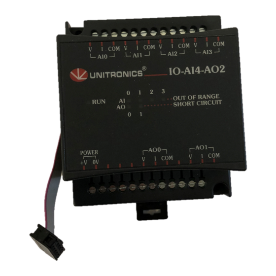
IO-AI4-AO2
I/O Expansion Module 4 Analog Inputs, 2 Analog Outputs
The IO-AI4-AO2 is an I/O expansion
module that can be used in conjunction
with specific Unitronics OPLC controllers.
The module offers 4 12-bit analog inputs;
functioning at 0-10V, 0-20mA, 4-20mA;
and 2 12-bit +sign analog outputs;
functioning at ±10V, 0-20mA, 4-20mA.
The interface between the module and the
OPLC is provided by an adapter.
The module may either be snap-mounted
on a DIN rail, or screw-mounted onto a
mounting plate.
Component identification
1
Module-to-module connector
2
Communication status indicator
3
Connection points for power
supply to analog unit
4
Output connection points
5
Input/Output status indicators
6
Module-to-module connector port
7
Input connection points
Before using this product, it is the responsibility of the user to read and understand this document and
any accompanying documentation.
All examples and diagrams shown herein are intended to aid understanding, and do not guarantee
operation. Unitronics accepts no responsibility for actual use of this product based on these examples.
Please dispose of this product in accordance with local and national standards and regulations.
Only qualified service personnel should open this device or carry out repairs.
User safety and equipment protection guidelines
This document is intended to aid trained and competent personnel in the installation of this equipment as
defined by the European directives for machinery, low voltage, and EMC. Only a technician or engineer trained
in the local and national electrical standards should perform tasks associated with the device's electrical wiring.
Symbols are used to highlight
information relating to the user's
personal safety and equipment
protection throughout this document.
When these symbols appear, the
associated information must be read
carefully and understood fully.
Failure to comply with appropriate safety guidelines can result in severe personal injury or
property damage. Always exercise proper caution when working with electrical equipment.
Unitronics Industrial Automation
V
I
COM
V
AI0
AI1
1
AI
AO
2
POWER
+V 0V
3
Symbol
Meaning
Description
The identified danger causes physical
Danger
and property damage.
The identified danger can cause
Warning
physical and property damage.
Caution
Caution
Use caution.
I
COM
V
I
COM
V
I
COM
AI2
AI3
IO-AI4-AO 2
OUT OF RANGE
SHORT CIRCUIT
AO 0
AO1
V
I
COM
V
I
COM
7
6
5
4
1
Advertisement
Table of Contents

Related Manuals for Unitronics IO-AI4-AO2


Summary of Contents for Unitronics IO-AI4-AO2
- Page 1 All examples and diagrams shown herein are intended to aid understanding, and do not guarantee operation. Unitronics accepts no responsibility for actual use of this product based on these examples. Please dispose of this product in accordance with local and national standards and regulations.
-
Page 2: Environmental Considerations
Snap the device onto the DIN rail as shown below; the module will be squarely situated on the DIN rail. 80mm (3.15") Screw-Mounting The figure on the next page is drawn to scale. It may be used as a guide for screw-mounting the module. Mounting screw type: either M3 or NC6-32. Unitronics Industrial Automation... - Page 3 6/03 IO-AI4-AO 2 I/O Expansion M odule 80mm (3.15") 5.8mm 68.4mm (0.228") (2.693") (0.16") 4mm (x2) (0.16") Unitronics Industrial Automation...
-
Page 4: Wiring Procedures
To avoid damaging the wire, do not exceed a maximum torque of 0.5 N·m (5 kgf·m). Do not use tin, solder, or any other substance on stripped wire that might cause the wire strand to break. Install at maximum distance from high-voltage cables and power equipment. Unitronics Industrial Automation... - Page 5 2 wire connection 3 wire connection Voltage Input Current Power transmitter supply 4 wire connection IO-AI4-AO2 OUT OF RANGE SHORT CIRCUIT POWER AO 1 +V 0V Power supply Circuit protection device LOAD LOAD Voltage Current connection connection Unitronics Industrial Automation...
-
Page 6: Output Wiring
In the event of voltage fluctuations or non-conformity to voltage power supply specifications, connect the device to a regulated power supply. The 24VDC power supply must be turned on and off simultaneously with the controller’s power supply. Unitronics Industrial Automation... - Page 7 6/03 IO-AI4-AO 2 I/O Expansion M odule IO-AI4-AO2 Technical Specifications Max. current consumption 30mA maximum from the adapter’s 5VDC 0.1W @ 5VDC Typical power consumption Status indicator (RUN) Green LED: —Lit when a communication link is established between module and OPLC.
- Page 8 Unitronics reserves the right to revise this publication from time to time and to amend its contents and related hardware and software at any time. Technical updates (if any) may be included in subsequent editions (if any).
-
Page 9: Analog Inputs
All examples and diagrams shown herein are intended to aid understanding, and do not guarantee operation. Unitronics accepts no responsibility for actual use of this product based on these examples. Please dispose of this product in accordance with local and national standards and regulations. - Page 10 Do not place in water or let water leak onto the unit. Do not allow debris to fall inside the unit during installation. Mounting the Module DIN-rail mounting Snap the device onto the DIN rail as shown below; the module will be squarely situated on the DIN rail. 80mm (3.15") Unitronics...
-
Page 11: Connecting Expansion Modules
Note that there is a protective cap provided with the adapter. This cap covers the port of the final I/O module in the system. To avoid damaging the system, do not connect or disconnect the device when the power is on. Component identification Module-to-module connector Protective cap Unitronics... - Page 12 The adapter and the COM signals of the analog inputs must be connected to the same 0V signal. The COM signals of each channel are internally shorted. When set to current/voltage, each 2 inputs share a common COM signal. Unitronics...
-
Page 13: Opening The Device
Open the first side of the device by inserting the blade between the 2 plastic moldings as shown below, then gently pushing up. Taking care not to damage the cable, open the other side of the device by inserting the blade where shown below, then gently pushing up. Gently remove the top of the device as shown. Unitronics... -
Page 14: Jumper Settings
To open the device and access the jumpers, refer to the instructions beginning on page 5. Caution Incompatible jumper settings and wiring may severely damage the device. Jumper # Voltage* Current Input 0 Input 1 Input 2 Input 3 Input 4 Input 5 Input 6 Input 7 * Default factory setting. Unitronics... - Page 15 The voltage or current value of analog inputs can also indicate faults, as shown in the table below. Value: 12-bit Value: 14-bit Input Value (Fast mode) (Normal mode) Deviates: Slightly below the input range. 4096 16384 Slightly above the input range. 32767 32767 Greatly above or below the input range. Unitronics...
- Page 16 I 149, 149 = 32 + 7 • 16 + 5 The information in this document reflects products at the date of printing. Unitronics reserves the right, subject to all applicable laws, at any time, at its sole discretion, and without notice, to discontinue or change the features, designs, materials and other specifications of its products, and to either permanently or temporarily withdraw any of the forgoing from the market.
-
Page 17: Isolated Analog Outputs
All examples and diagrams shown herein are intended to aid understanding, and do not guarantee operation. Unitronics accepts no responsibility for actual use of this product based on these examples. Please dispose of this product in accordance with local and national standards and regulations. - Page 18 Snap the device onto the DIN rail as shown below; the module will be squarely situated on the DIN rail. 80mm (3.15") Screw-Mounting The figure on the next page is drawn to scale. It may be used as a guide for screw-mounting the module. Mounting screw type: either M3 or NC6-32. Unitronics Industrial Automation...
- Page 19 5/03 IO - AO 6X I / O E x p a n s i o n M o d u l e 80mm (3.15") 5.8mm 68.4mm (0.228") (2.693") (0.16") 4mm (x2) (0.16") Unitronics Industrial Automation...
- Page 20 To avoid damaging the wire, do not exceed a maximum torque of 0.5 N·m (5 kgf·m). Do not use tin, solder, or any other substance on stripped wire that might cause the wire strand to break. Install at maximum distance from high-voltage cables and power equipment. Unitronics Industrial Automation...
-
Page 21: Analog Outputs
Do not connect the ‘Neutral’ or ‘Line’ signal of the 110/220VAC to the device’s 0V pin. In the event of voltage fluctuations or non-conformity to voltage power supply specifications, connect the device to a regulated power supply. Unitronics Industrial Automation... - Page 22 Note that the range of each I/O is defined both by wiring and within the controller’s software. When an analog output is set to use current, the output must be connected before the power is turned on. Unitronics Industrial Automation...
- Page 23 RO8 is always assigned the number 7. Its I/Os are addressed accordingly. Example Input #5, located on an EX90-DI8-RO8 connected to an M90 OPLC will be addressed as I 149, 149 = 32 + 7 • 16 + 5 Unitronics Industrial Automation...
- Page 24 Unitronics products referred to herein in any manner deviating from the recommendations made in this document. Unitronics assumes no responsibility for the use of any parts, components, or other ancillary appliances including circuitry other than as recommended hereunder or other than that embodied in the Unitronics product.
- Page 25 All examples and diagrams shown herein are intended to aid understanding, and do not guarantee operation. Unitronics accepts no responsibility for actual use of this product based on these examples. Please dispose of this product in accordance with local and national standards and regulations.
-
Page 26: Mounting The Module
Do not allow debris to fall inside the unit during installation. Mounting the Module DIN-rail mounting Snap the device onto the DIN rail as shown below; the module will be squarely situated on the DIN rail. 80mm (3.15") Unitronics Industrial Automation... - Page 27 Screw-Mounting The figure below is not drawn to scale. It may be used as a guide for screw-mounting the module. Mounting screw type: either M3 or NC6-32. 80mm (3.15") 5.8mm 68.4mm (0.228") (2.693") (0.16") 4mm (x2) (0.16") Unitronics Industrial Automation...
- Page 28 Input or output cables should not be run through the same multi-core cable or share the same wire. Allow for voltage drop and noise interference with input lines used over an extended distance. Use wire that is properly sized for the load. Unitronics Industrial Automation...
-
Page 29: Analog Inputs
The adapter and the COM signals of the analog inputs must be connected to the same 0V signal. The COM signals of each channel are internally shorted. When set to current/voltage, each 2 inputs share a common COM signal. Unitronics Industrial Automation... - Page 30 Open the first side of the device by inserting the blade between the 2 plastic moldings as shown below, then gently pushing up. Taking care not to damage the cable, open the other side of the device by inserting the blade where shown below, then gently pushing up. Unitronics Industrial Automation...
- Page 31 I / O E x p a n s i o n M o d u l e Gently remove the top of the device as shown. The jumpers are shown at right. Change the jumper settings as required, in accordance with the tables shown on the next page. Unitronics Industrial Automation...
- Page 32 To open the device and access the jumpers, refer to the instructions beginning on page 6. Caution Incompatible jumper settings and wiring may severely damage the device. Jumper # Thermocouple* Voltage Current Input 0 Input 1 Input 2 Input 3 Input 4 Input 5 Input 6 Input 7 * Default factory setting. Unitronics Industrial Automation...
- Page 33 + White (32 to 3214°F) - Red - Blue 0 to 1768°C + Black + White (32 to 3214°F) - Red - Blue -200 to 400°C + Blue + White (-328 to 752°F) - Red - Blue Unitronics Industrial Automation...
- Page 34 The voltage or current value of analog inputs can also indicate faults, as shown in the table below. Value: 12-bit Value: 14-bit Input Value (Fast mode) (Normal mode) Deviates: Slightly below the input range. 4096 16384 Slightly above the input range. 32767 32767 Greatly above or below the input range. Unitronics Industrial Automation...
- Page 35 RO8 is always assigned the number 7. Its I/Os are addressed accordingly. Example Input #5, located on an EX90-DI8-RO8 connected to an OPLC will be addressed as I 149, 149 = 32 + 7 • 16 + 5 Unitronics Industrial Automation...
- Page 36 Unitronics products referred to herein in any manner deviating from the recommendations made in this document. Unitronics assumes no responsibility for the use of any parts, components, or other ancillary appliances including circuitry other than as recommended hereunder or other than that embodied in the Unitronics product.
- Page 37 All examples and diagrams shown herein are intended to aid understanding, and do not guarantee operation. Unitronics accepts no responsibility for actual use of this product based on these examples. Please dispose of this product in accordance with local and national standards and regulations.
- Page 38 Do not allow debris to fall inside the unit during installation. Mounting the Module DIN-rail mounting Snap the device onto the DIN rail as shown below; the module will be squarely situated on the DIN rail. 80mm (3.15") Unitronics Industrial Automation...
- Page 39 Screw-Mounting The figure below is not drawn to scale. It may be used as a guide for screw-mounting the module. Mounting screw type: either M3 or NC6-32. 80mm (3.15") 5.8mm 68.4mm (0.228") (2.693") (0.16") 4mm (x2) (0.16") Unitronics Industrial Automation...
- Page 40 Input or output cables should not be run through the same multi-core cable or share the same wire. Allow for voltage drop and noise interference with input lines used over an extended distance. Use wire that is properly sized for the load. Unitronics Industrial Automation...
-
Page 41: External Power Supply
Do not earth the module via the Loadcell cable shield. External power supply and Digital I/O wiring See Earthing the module guidelines above. Digital I/Os Refer to External power supply and Digital I/O wiring above for wiring guidelines. Unitronics Industrial Automation... - Page 42 The cable shield should be connected ONLY to the Loadcell chassis. The shield at the other end of the cable should be left unconnected. Refer to the figures below for wiring guidelines. 6 wire Loadcell wiring 4 wire Loadcell wiring Unitronics Industrial Automation...
- Page 43 200mA maximum (up to 12 x 350Ω Loadcells) Per Loadcell input 200mA maximum (up to 12 x 350Ω Loadcells) Total Yes, up to 1 minute Short circuit protection A/D Converter Sigma–Delta Conversion method 24 bits Resolution 12.5msec (80Hz) Conversion period Unitronics Industrial Automation...
- Page 44 Green LED—Lit when the input is active. See Note 5. (IN) Digital Outputs Number of outputs 2 pnp (source) Output type P-MOSFET (open drain) Galvanic isolation Dig. output to ext. pwr supply Dig. output to bus Dig. output to Loadcell Dig. output to digital input Unitronics Industrial Automation...
- Page 45 AC excitation has the advantage of lower offset drift errors, improving performance over time and in the presence of ambient temperature changes. To minimize the impact of offset drift errors in your loadcell application, the use of AC excitation is recommended. Unitronics Industrial Automation...
-
Page 46: Effective Resolution
The number of Loadcell inputs used per expansion module affects the sampling rate for each of them, resulting in lower filter depth and effective resolution. The filter settling time can be programmed separately for each Loadcell input without affecting the other(s). Unitronics Industrial Automation... - Page 47 RO8 is always assigned the number 7. Its I/Os are addressed accordingly. Example Input #5, located on an EX90-DI8-RO8 connected to an OPLC will be addressed as I 149, 149 = 32 + 7 • 16 + 5 Unitronics Industrial Automation...
- Page 48 Unitronics products referred to herein in any manner deviating from the recommendations made in this document. Unitronics assumes no responsibility for the use of any parts, components, or other ancillary appliances including circuitry other than as recommended hereunder or other than that embodied in the Unitronics product.
-
Page 49: I/O Expansion Modules
All examples and diagrams shown herein are intended to aid understanding, and do not guarantee operation. Unitronics accepts no responsibility for actual use of this product based on these examples. Please dispose of this product in accordance with local and national standards and regulations. - Page 50 Do not place in water or let water leak onto the unit. Do not allow debris to fall inside the unit during installation. Mounting the Module DIN-rail mounting Snap the device onto the DIN rail as shown below; the module will be squarely situated on the DIN rail. 80mm (3.15") Unitronics...
- Page 51 I / O E x p a n s i o n M o d u l e s Screw-Mounting The figure below is not drawn to scale. It may be used as a guide for screw-mounting the module. Mounting screw type: either M3 or NC6-32. 80mm (3.15") 5.8mm 68.4mm (0.228") (2.693") (0.16") 4mm (x2) (0.16") Unitronics...
- Page 52 To avoid damaging the wire, do not exceed a maximum torque of 0.5 N·m (5 kgf·cm). Do not use tin, solder, or any other substance on stripped wire that might cause the wire strand to break. Install at maximum distance from high-voltage cables and power equipment. Unitronics...
- Page 53 Shields should be connected at the signal source. 2 wire connection 3 wire connection PT1000/NI1000 4 wire connection * RTD input types PT1000/NI1000 support a two-wire connection, because the high resistance (1000 ohm) of the sensor element compensates for voltage drop. Unitronics...
- Page 54 Storage temperature -20° to 60°C (-4 to 140° F) Relative Humidity (RH) 10% to 95% (non-condensing) Dimensions (WxHxD) 80 x 93 x 60mm (3.15 x 3.66 x 2.362”) Weight 140.3g (4.94oz.) Mounting Either onto a 35mm DIN-rail or screw-mounted. Unitronics...
- Page 55 10000 (1000°) Input temperature is out of the permissible range (PT: over 460°C) (NI: over 232° C) (NI120: over 172°C) Sensor is not connected to input +I or +V signals are not connected -I and –V signals are not connected Unitronics...
- Page 56 Unitronics website at http://www.unitronics.com/. The information in this document reflects products at the date of printing. Unitronics reserves the right, subject to all applicable laws, at any time, at its sole discretion, and without notice, to discontinue or change the features, designs, materials and other specifications of its products, and to either permanently or temporarily withdraw any of the forgoing from the market.
Need help?
Do you have a question about the IO-AI4-AO2 and is the answer not in the manual?
Questions and answers