Advertisement
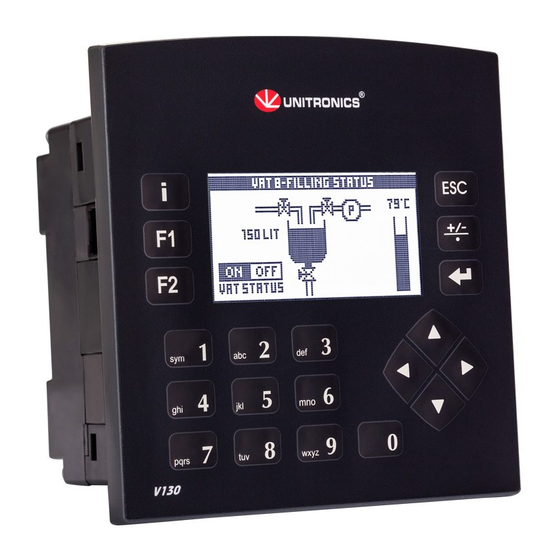
Vision™ OPLC™
This guide shows you how to install an additional communication module in a Vision130™ or
Vision350™ or Vision430™ or SM35™ or SM43™ or SM70™ controller. Instructions are included
for modules:
V100-17-RS4 (RS232/RS485,non-isolated), V100-17-RS4X (RS232/RS485,isolated)
V100-17-ET2 (Ethernet), V100-S-ET2 (Ethernet-Wide Temperature)
V100-17-PB1 (PROFIBUS slave supported by Vxxx Series Only)
Danger Symbols
Symbol
Meaning
Danger
Warning
Caution
Caution
Before using this product, the user must read and understand this document.
All examples and diagrams are intended to aid understanding, and do not guarantee operation.
Unitronics accepts no responsibility for actual use of this product based on these examples.
Please dispose of this product according to local and national standards and regulations.
Only qualified service personnel should open this device or carry out repairs.
Failure to comply with appropriate safety guidelines can cause severe injury or property
damage.
Do not attempt to use this device with parameters that exceed permissible levels.
To avoid damaging the system, do not connect/disconnect the device when power is on.
Environmental Considerations
Do not install in areas with: excessive or conductive dust, corrosive or flammable gas,
moisture or rain, excessive heat, regular impact shocks or excessive vibration.
Do not place in water or let water leak onto the unit.
Do not allow debris to fall inside the unit during installation.
General
Turn off power before making communications connections.
Do not touch live wires
Unused pins should not be connected. Ignoring this directive may damage the device.
Double-check all wiring before turning on the power supply.
Installation Instructions
This section comprises all of the installation procedures for each of the modules.
Installing modules also requires you to remove and replace PCB boards already
installed in the controller.
Caution
Make certain that the pins fit correctly into their matching receptacle.
Unitronics
Installation Guide, V130/V350/V430/SM35/SM43/SM70 COM
Modules V100-17-RS4/X, V100-17-ET2, V100-S-ET2, V100-17-PB1
Description
The identified danger causes physical and property damage.
The identified danger could cause physical and property damage.
Use caution.
Advertisement
Table of Contents

Summary of Contents for Unitronics Vision OPLC V130
- Page 1 All examples and diagrams are intended to aid understanding, and do not guarantee operation. Unitronics accepts no responsibility for actual use of this product based on these examples. Please dispose of this product according to local and national standards and regulations.
- Page 2 Separate IG is provided for this procedure V130 only 2. Remove the keypad ribbon cable shown in the accompanying figure. a. Press the sides of the cable connector and pull it slightly upwards; this releases the cable. b. Pull the cable from the connector. Unitronics...
- Page 3 - V100-17-ET2, V100-S-ET2 or V100-17-PB1 Return plastic tab A over the new port. 8. Replace the main board, including the fastening screws. V130 only 1. Replace the ribbon cable. 2. Push the cable connector down to lock the cable in place. Unitronics...
- Page 4 The tradenames, trademarks, logos and service marks presented in this document, including their design, are the property of Unitronics (1989) (R"G) Ltd. or other third parties and you are not permitted to use them without the prior written consent of Unitronics or such third party as may own them...


Need help?
Do you have a question about the Vision OPLC V130 and is the answer not in the manual?
Questions and answers