Advertisement
Quick Links
V100-17-RS4 V100-17-RS4X
This guide provides specifications for Unitronics’ communication modules
V100-17-RS4, V100-17-RS4X.
You can find additional information, such as wiring diagrams, in the product’s installation guide located
on the Unitronics’ Setup CD and in the Technical Library at www.unitronics.com.
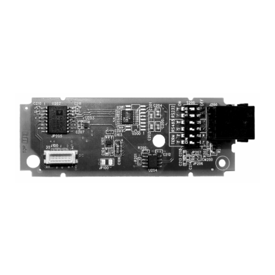
V100-17-RS4 (not isolated) V100-17-RS4X (isolated) Serial Modules
Use these modules to add an additional serial communication port to the controller.
Use RS232 to download programs from a PC, and to communicate with serial devices
and applications, such as SCADA.
Use RS485 to create a multi-drop network containing up to 32 devices.
The modules are identical except for isolation. Module ports are type RJ-11 and may be set to
either RS232 or RS485 via wiring and DIP switch settings, in accordance with the table on
page 2.
To connect a PC to a port that is set to RS485, remove the RS485 connector, and connect the PC
to the PLC via the programming cable. Note that this is possible only if flow control signals are not
used (which is the standard case).
Standard Kit contents
RS232/485 Module
RS485 cable
Signals are related to the controller’s 0V; the same 0V is used by the power supply.
Do not connect the device directly to a telephone or telephone line.
Note that the V100-17-RS4 port is not isolated. If the controller is used with a non-
Caution
isolated external device, avoid potential voltage that exceeds ± 10V. To avoid
damaging the system, all non-isolated device ports should relate to the same ground
signal.
Pinouts
The pinouts below show the PLC port signals.
RS232
Pin #
Description
1*
DTR signal
2
0V reference
3
TXD signal
4
RXD signal
5
0V reference
6*
DSR signal
*Standard programming cables do not provide connection points for pins 1 and 6.
**When a port is adapted to RS485, Pin 1 (DTR) is used for signal A,
and Pin 6 (DSR) signal is used for signal B.
Unitronics
RS485**
Pin #
Description
1
A signal (+)
2
(RS232 signal)
3
(RS232 signal)
4
(RS232 signal)
5
(RS232 signal)
6
B signal (-)
RS232/485 Module
Controller Port
Pin #1
5 / 2011
www.klinkmann.com
Advertisement

Subscribe to Our Youtube Channel
Related Manuals for Unitronics V100-17-RS4


Summary of Contents for Unitronics V100-17-RS4
- Page 1 Signals are related to the controller’s 0V; the same 0V is used by the power supply. Do not connect the device directly to a telephone or telephone line. Note that the V100-17-RS4 port is not isolated. If the controller is used with a non- Caution isolated external device, avoid potential voltage that exceeds ±...
- Page 2 Switch Settings RS232* RS485 RS485 with termination** *Default factory setting **Causes the unit to function as an end unit in an RS485 network V100-17-RS4 V100-17-RS4X Technical Specifications RS232 Port Specifications ±20V Voltage limits Input voltage ±20VDC absolute maximum Cable length...
Need help?
Do you have a question about the V100-17-RS4 and is the answer not in the manual?
Questions and answers