Advertisement
Quick Links
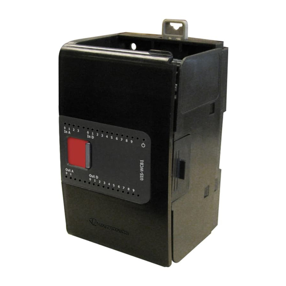
Uni-I/O™ Wide
Modules
Uni-I/O™ Wide is a family of Input/Output modules that are compatible with the
UniStream™ control platform. Wide Modules are 1.5 times as wide as Uni-I/O™ modules,
and comprise more I/O points in less space.
This guide provides basic installation information for UIS-WCB1 Uni-I/O™ module.
Technical specifications may be downloaded from the Unitronics website.
The UniStream™ platform
comprises CPU controllers, HMI
panels, and local I/O modules
that snap together to form an
all-in-one Programmable Logic
Controller (PLC).
Install Uni-I/O™ modules:
Onto the back of any
UniStream™ HMI Panel
comprising a CPU-for-Panel.
Onto a DIN-rail, using a
Local Expansion Kit.
The maximum number of Uni-I/O™ Wide modules that can be connected to a single CPU
controller is limited. For details, please refer to the specification sheets of the
UniStream™ CPU or any of the relevant Local Expansion Kits.
Before You Begin
Before installing the device, the installer must:
Read and understand this document.
Verify the Kit Contents.
Installation option requirements
If you are installing a Uni-I/O™ module onto:
A UniStream™ HMI Panel; the Panel must comprise a CPU-for-Panel, installed according
to the CPU-for-Panel installation guide.
A DIN-rail; you must use a Local Expansion Kit, available by separate order, to integrate
the Uni-I/O™ modules on the DIN-rail into a UniStream™ control system.
Alert Symbols and General Restrictions
When any of the following symbols appear, read the associated information carefully.
Symbol
Meaning
Danger
Warning
Caution
Caution
All examples and diagrams are intended to aid understanding, and do not guarantee
operation. Unitronics accepts no responsibility for actual use of this product based on
these examples.
Please dispose of this product according to local and national standards and regulations.
Unitronics
Description
The identified danger causes physical and property damage.
The identified danger could cause physical and property damage.
Use caution.
Installation Guide
UIS-WCB1
1
Advertisement

Subscribe to Our Youtube Channel
Related Manuals for Unitronics Uni-I/O UIS-WCB1


Summary of Contents for Unitronics Uni-I/O UIS-WCB1
- Page 1 Use caution. All examples and diagrams are intended to aid understanding, and do not guarantee operation. Unitronics accepts no responsibility for actual use of this product based on these examples. Please dispose of this product according to local and national standards and regulations.
-
Page 2: Environmental Considerations
Slide the Bus Connector Lock to the left, to electrically connect Lock the Uni-I/O™ module to the CPU or adjacent module. I/O Bus - Right Right-Side Connector, shipped covered. Leave covered when not in use. Bus Connector Cover I/Os I/O connection points Unitronics... -
Page 3: Installation
3. Use the upper and lower guide-tunnels (tongue & groove) to slide the Uni- I/O™ module into place. 4. Verify that the DIN-rail clips located at the top and bottom of the Uni-I/O™ module have snapped onto the DIN-rail. Unitronics... - Page 4 All power supplies in the system must include double insulation. Power supply outputs must be rated as SELV/PELV/Class 2/Limited Power. Do not connect either the ‘Neutral’ or ‘Line’ signal of the 110/220VAC to device’s 0V point. Do not touch live wires. Unitronics...
- Page 5 Two top groups Input connection points Two bottom groups Outputs and power supply connection points The function of certain I/Os may be adapted via wiring and software settings. Unitronics...
- Page 6 Ensure shield continuity when extending shielded cables. For detailed information, refer to the document System Wiring Guidelines, located in the Technical Library in the Unitronics’ website. Wiring the Power Supply This module requires an external, regulated 24VDC power supply.
- Page 7 The mode is determined both by wiring and by the hardware configuration within the software application. Voltage and current modes use distinct points. Connect only the point associated with the selected mode; leave the other point unconnected. Unitronics...
- Page 8 UIS-WCB1 Installation Guide Voltage Differential Single-ended Current 2-wire 3-wire 4-wire Unitronics...
- Page 9 When connecting 3- or 4-wire RTDs, make sure to use conductors of the same type, width, and length for all RTD wires, otherwise module accuracy will degrade. When connecting 4-wire RTDs, use 3-wire cable and leave the unused wire unconnected with minimal length. Unitronics...
- Page 10 To increase the life span of the relay contacts and protect the module from potential damage by reverse EMF, connect: a clamping diode in parallel with each inductive DC load. an RC snubber circuit in parallel with each inductive AC load. DC Load AC Load Unitronics...
- Page 11 CM2 or CM3 to the system 0V. Do not use points CM2 or CM3 for any purpose other than connecting the analog output load. Using them for any other purpose may damage the module. Unitronics...
- Page 12 Current The information in this document reflects products at the date of printing. Unitronics reserves the right, subject to all applicable laws, at any time, at its sole discretion, and without notice, to discontinue or change the features, designs, materials and other specifications of its products, and to either permanently or temporarily withdraw any of the forgoing from the market.
Need help?
Do you have a question about the Uni-I/O UIS-WCB1 and is the answer not in the manual?
Questions and answers