Table of Contents
Advertisement
Quick Links
Advertisement
Table of Contents

Related Manuals for Bticino Switchboard


Summary of Contents for Bticino Switchboard
- Page 1 346310 Switchboard Installer manual...
-
Page 3: Table Of Contents
Switchboard Contents Introduction Warnings and recommendations What’s in your box Description Main functions Front view Video door entry system function keys Navigation keys Back view Installation Settings Handset (IU) D/N 12 Function Slave handset (IU) Modify contact Time bands Automations... -
Page 4: Introduction
- must only be installed indoors; - must be kept away from water drips and sprays; - must only be used in conjunction with BTicino 2 wire digital video door entry systems. What’s in your box In your box you will find: •... -
Page 5: Description
It gives the possibility of receiving and managing alarms from apartment or common areas. NOTE: The switchboard is unable to manage the calls from riser Entrance Panels “EP” (i.e. entrance panels installed downstream interface 346851). Calls from riser Entrance Panels... -
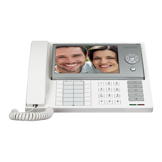
Page 6: Front View
5 Cancel key 6 Direct call key 7 Door lock key 8 Directory key 9 Entrance panel activation and cycling key 10 Handsfree key 11 Active alarm LED 12 Switchboard status LED 13 Alphanumeric keypad 14 Configurable function keypad 15 Handsfree loudspeaker... -
Page 7: Video Door Entry System Function Keys
When idle, the door lock of the associated Entrance Panel opens. Directory key It displays the handset, entrance panel, and switchboard directory screen. Entrance Panel/ Cycle mode activation It switches the associated Entrance Panel on and enables cycling through any other Entrance Panels or cameras present. -
Page 8: Back View
2 Description Back view 1 Mini-USB connector for connection to the PC 2 End of line ON/OFF micro switch 3 Connection to the BTicino 2 wire digital system BUS 4 Additional power supply connector (1-2) 5 Optional siren contact connector... -
Page 9: Installation
Switchboard 3 Installation 1 Remove the cover from the base 2 Insert the cable in the appropriate slot 3 Connect to the bus (and to the additional power supply if required) 4 Replace the cover... -
Page 10: Settings
4 Settings After connecting and powering the switchboard, press OK to display the main menu. After connecting and powering the switchboard, press After connecting and powering the switchboard, press After connecting and powering the switchboard, press After connecting and powering the switchboard, press... - Page 11 Switchboard Enter the password using the keypad P a s s w o r d : (default password: 12345) * * * * * Press OK to confirm The following icon screen appears: 1 Handset (IU) D/N function 2 Slave handset (IU)
-
Page 12: Handset (Iu) D/N 12 Function
4 Settings Handset (IU) D/N function This can be used to enable or disable the handset “Day/Night” function. Select the handset D/N function Press OK to access the menu D / N F u n c t i o n D / N F u n c t i o n Press OK repeatedly to enable/disable... -
Page 13: Slave Handset (Iu)
Switchboard Slave handset (IU) It can be used to enable or disable the slave handset (temporarily answer any calls received by the switchboard), and to configure the corresponding address. Select the slave handset function Press OK to access the menu... -
Page 14: Modify Contact
4 Settings Modify contact It can be used to create, change, or delete the contacts in the various directories. Select the Modify Contact function Press OK to access the menu M o d i f y C o n t a c t C h a n g e C o n t a c t A d d r e s s... - Page 15 Switchboard - Create Move the cursor to the existing parame- I n t e r n a l U n i t ters in succession Press OK to highlight data for which the > S C S A d d r .
- Page 16 4 Settings WARNING: The switchboard makes direct calls using the logic addresses. - Delete D e l e t e Move the cursor to the contact to delete A p a r t m e n t Press OK to delete the contact...
-
Page 17: Time Bands
For each day of the week, it is possible to set up to 3 day start and night start time bands, upon which the switchboard will automatically switch from one status to the other. NOTE: This mode is active when the “Day/Night” function of the configuration menu is set to auto- matic (see User Manual). -
Page 18: Automations
4 Settings Automations This function can be used to configure up to 5 entrance panels, so that the corresponding door locks can be released when no calls are active from the entrance panel. Select the Automation function Press OK to access the menu A u t o m a t i o n L o c k C o n f i g u r a t i o n... -
Page 19: Function Key Setup
R i s e r List of configurable functions: Door lock 1 to 5 Handset Day/Night Entrance panel Day/Night Presence status Slave handset Staircase light Handset Call Entrance panel Call Switchboard call __ _ __ _ _ __ _ _ ___ (not configured) -
Page 20: Alarm Setup
It can be used to enable or disable: - alarms (burglar alarms, panic alarms, technical alarms) - the contact for the external siren (or luminous signalling ), accessible from the back of the switchboard Select the Alarm Setup function Press OK to access the menu... -
Page 21: Configuration
Switchboard Configuration This function enables the initial configuration through: - local switchboard address setup: - associated entrance panel address setup; - associated camera enabling/disabling; - directory type selection (type 1: alphanumeric; type 2: coding (BPI); - selection of the navigation language. - Page 22 A s s o c i a t e d S w i t c h b . Use the keypad to change the value M a i n Press OK to confirm NOTE: If only one switchboard is present, this must be configured as primary switchboard, with local address 0.
- Page 23 Switchboard Press OK to confirm A s s o c i a t e d L i s t Press OK repeatedly to move the cursor to the desired EP I n d . S c s Move the cursor to the SCS...
-
Page 24: Change Password
4 Settings Change password This function is used to change the password for access to the Installation setup section. The de- fault password is 12345. Select the Change Password function Press OK to confirm C h a n g e P a s s w o r d Enter the new password using the keypad (max. -
Page 25: Advanced Configuration
Switchboard 5 Advanced configuration As an alternative to the menu setup, it is also possible to configure the switchboard from the PC, using the TiSwitchBoardDevice software found in the CD supplied. WARNING Some functions, like the creation of the directories and the management of the bells, can only be performed using the software. -
Page 26: Troubleshooting
6 Troubleshooting Problem Solution - check that the switchboard is correctly wired No image appears when the Entrance Panel/ appears and configured; Cycling key is pressed - the audio/video channel may be busy, wait for it to become free and try again... -
Page 27: Appendix
Switchboard 7 Appendix TECHNICAL DATA from SCS BUS: 19 - 27 V Power supply from 12: 18 - 27 V Absorption (Max) from 20 mA (A/V connection - at the minimum operating voltage) BUS with additional 5 mA (in stand-by) - Page 28 BTicino SpA Via Messina, 38 20154 Milano - Italy www.bticino.com BTicino SpA reserves at any time the right to modify the contents of this booklet and to communicate, in any form and modality, the changes brought to the same.
Need help?
Do you have a question about the Switchboard and is the answer not in the manual?
Questions and answers