Advertisement
Available languages
Available languages
Quick Links
Page 1 of 20
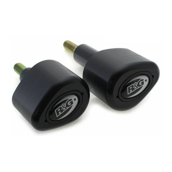
CP0492BL
FITTING INSTRUCTIONS FOR CP0492BL
AERO-STYLE CRASH PROTECTORS
TRIUMPH TIGER 900 2020-
T
.
HIS KIT CONTAINS THE ITEMS PICTURED AND LABELLED OVER PAGE
S
.
OME PARTS MAY BE SHOWN FOR CLARITY OF INSTRUCTIONS ONLY
D
.
O NOT PROCEED UNTIL YOU ARE SURE ALL PARTS ARE PRESENT
P
.
LEASE READ ALL INSTRUCTIONS BEFORE PROCEEDING
IF IN ANY DOUBT WHEN FITTING OUR PRODUCTS, CONSULT ONE OF OUR DEALERS
OR HAVE FITTED BY A QUALIFIED TECHNICIAN.
P
LEASE NOTE THAT THE WAY THE KIT IS PACKED DOES NOT NECESSARILY REPRESENT THE WAY OF
.
MOUNTING TO THE BIKE
I
,
N THE EVENT OF RUBBER WASHERS BEING USED TO HOLD COMPONENTS ONTO BOLTS
.
THESE RUBBER WASHERS CAN BE THROWN AWAY
DIGITAL COPIES OF THESE INSTRUCTIONS ARE AVAILABLE FROM:
WWW.RG-RACING.COM
R&G Racing
Unit 1, Shelley's Lane, East Worldham, Alton, Hampshire, GU34 3AQ
Tel: +44 (0)1420 89007 Fax: +44 (0)1420 87301
www.rg-racing.com
Email:
info@rg-racing.com
Advertisement

Subscribe to Our Youtube Channel
Related Manuals for R&G CP0492BL


Summary of Contents for R&G CP0492BL
- Page 1 Page 1 of 20 CP0492BL FITTING INSTRUCTIONS FOR CP0492BL AERO-STYLE CRASH PROTECTORS TRIUMPH TIGER 900 2020- HIS KIT CONTAINS THE ITEMS PICTURED AND LABELLED OVER PAGE OME PARTS MAY BE SHOWN FOR CLARITY OF INSTRUCTIONS ONLY O NOT PROCEED UNTIL YOU ARE SURE ALL PARTS ARE PRESENT...
-
Page 2: Tools Required
Page 2 of 20 CP0492BL TOOLS REQUIRED GENERAL TORQUE SETTINGS • 17mm A/F SOCKET & WRENCH M4 BOLT = 8Nm M5 BOLT = • T50 TORX TOOL M6 BOLT = • 4 & 8mm A/F ALLEN TOOL M8 BOLT = 20Nm •... - Page 3 Page 3 of 20 CP0492BL AERO-STYLE CRASH PROTECTOR ORIENTATION LHS EXPLODED ASSEMBLY VIEW R&G Racing Unit 1, Shelley’s Lane, East Worldham, Alton, Hampshire, GU34 3AQ Tel: +44 (0)1420 89007 Fax: +44 (0)1420 87301 www.rg-racing.com Email: info@rg-racing.com...
- Page 4 Page 4 of 20 CP0492BL RHS EXPLODED ASSEMBLY VIEW FITTING PICTURES Picture 1 Picture 2 R&G Racing Unit 1, Shelley’s Lane, East Worldham, Alton, Hampshire, GU34 3AQ Tel: +44 (0)1420 89007 Fax: +44 (0)1420 87301 www.rg-racing.com Email: info@rg-racing.com...
- Page 5 Page 5 of 20 CP0492BL Picture 3 Picture 4 Picture 5 Picture 6 Picture 7 Picture 8 R&G Racing Unit 1, Shelley’s Lane, East Worldham, Alton, Hampshire, GU34 3AQ Tel: +44 (0)1420 89007 Fax: +44 (0)1420 87301 www.rg-racing.com Email: info@rg-racing.com...
- Page 6 Page 6 of 20 CP0492BL Picture 9 Picture 10 Picture 11 Picture 12 Picture 13 Picture 14 R&G Racing Unit 1, Shelley’s Lane, East Worldham, Alton, Hampshire, GU34 3AQ Tel: +44 (0)1420 89007 Fax: +44 (0)1420 87301 www.rg-racing.com Email: info@rg-racing.com...
-
Page 7: Fitting Instructions
Page 7 of 20 CP0492BL FITTING INSTRUCTIONS • Before fitting the R&G crash protectors, it is advised that a jack is positioned underneath the bike at a suitable point to support the weight of the engine during fitment. A small piece of wood should also be placed between the jack and the mounting point to help to spread the load. - Page 8 Page 8 of 20 CP0492BL • Offer the assembly up to the rearmost engine mounting hole and loosely tighten in position using an 8mm Allen tool, leaving enough room to access the front engine mounting bolt. As shown in picture 9, make sure to tuck the mounting block under the clutch cable to ensure it’s under no strain.
- Page 9 Page 9 of 20 CP0492BL NOTICE DE MONTAGE POUR CP0492BL PROTECTION CRASH LATÉRALE TRIUMPH TIGER 900 2020- E KIT CONTIENT LES ARTICLES ILLUSTRES ET ETIQUETES SUR LA PAGE ERTAINES PARTIES PEUVENT ETRE PRESENTES UNIQUEMENT POUR LA CLARTE DES INSTRUCTIONS E PAS PROCEDER AU MONTAGE TANT QUE VOUS N...
-
Page 10: Outils Requis
Page 10 of 20 CP0492BL OUTILS REQUIS VALEURS DE SERRAGE • CLÉ À CLIQUET + DOULLE 17mm M4 BOULON = 8Nm M5 BOULON = • CLÉ TORX T50 M6 BOULON = • CLÉS ALLEN 4 & 8mm M8 BOULON = 20Nm •... - Page 11 Page 11 of 20 CP0492BL PROTECTION CRASH LATÉRALE SCHÉMA CÔTÉ GAUCHE R&G Racing Unit 1, Shelley’s Lane, East Worldham, Alton, Hampshire, GU34 3AQ Tel: +44 (0)1420 89007 Fax: +44 (0)1420 87301 www.rg-racing.com Email: info@rg-racing.com...
-
Page 12: Notice De Montage
Page 12 of 20 CP0492BL SCHÉMA CÔTÉ DROIT NOTICE DE MONTAGE Avant de monter les protections crash R&G, il est conseillé de placer un cric sous • la moto à un endroit approprié pour supporter le poids du moteur pendant le montage. - Page 13 Page 13 of 20 CP0492BL • Présentez l'assemblage sur le trou de montage du moteur le plus reculé et serrez légèrement en position à l'aide d'une clé Allen de 8 mm, comme indiqué sur la photo 4, en laissant suffisamment d'espace pour accéder au boulon de montage du moteur avant. À l'aide d'un clé...
- Page 14 Page 14 of 20 CP0492BL • Rentrez le câble d'embrayage dans la rainure du bloc de montage comme indiqué sur la photo 11 et poussez un capuchon plat (article 15) dans les têtes des deux boulons comme indiqué sur la photo 13. Reposez maintenant le panneau latéral côté droit à l'aide d'une clé Allen 4mm.
- Page 15 Page 15 of 20 CP0492BL MONTAGEANLEITUNG FÜR CP0492BL AERO-STYLE STURZPADS TRIUMPH TIGER 900 2020- EILE SIND AUF DEN NACHFOLGENDEN EITEN ABGEBILDET UND GEKENNZEICHNET IE ABGEBILDETEN EILE DIENEN LEDIGLICH ZUR RKLÄRUNG Ü BERPRÜFEN IE ZUERST DASS ALLE EILE VORHANDEN SIND ESEN...
- Page 16 Page 16 of 20 CP0492BL SIE BENÖTIGEN FOLGENDE WERKZEUGE ALLGEM. ANZUGSDREHMOMENT • 17mm A/F STECKSCHLÜSSEL M4 SCHRAUBE = 8Nm M5 SCHRAUBE = • T50 TORX-SCHLÜSSEL M6 SCHRAUBE = • 4 & 8mm INBUSSCHLÜSSEL M8 SCHRAUBE = 20Nm • DREHMOMENTSCHLÜSSEL 0 SCHRAUBE = 40Nm...
- Page 17 Page 17 of 20 CP0492BL MOTORRAD HINTEN MOTORRAD VORNE LINKE SEITE – ZUSAMMENBAU EXPLOSIONSZEICHNUNG RECHTE SEITE – ZUSAMMENBAU EXPLOSIONSZEICHNUNG R&G Racing Unit 1, Shelley’s Lane, East Worldham, Alton, Hampshire, GU34 3AQ Tel: +44 (0)1420 89007 Fax: +44 (0)1420 87301 www.rg-racing.com Email: info@rg-racing.com...
- Page 18 Page 18 of 20 CP0492BL MONTAGEANLEITUNG • Bevor Sie die R&G Sturzpads montieren, empfehlen wir, einen Heber an einem geeigneten Montagepunkt unter das Motorrad zu stellen, um somit das Gewicht des Motors während der Montage zu stützen. Ein kleines Stück Holz sollte zusätzlich zwischen Montagepunkt und Heber platziert werden, um die Last zu verteilen.
- Page 19 Page 19 of 20 CP0492BL • Die Einheit an die hinterste Montageöffnung für den Motor ansetzen und mit einem 8mm Inbusschlüssel lose in Position fixieren wie in Abbildung 4 abgebildet. Lassen Sie genug Platz, um Zugang zur vorderen Montageschraube für den Motor zu ermöglichen. Mit einem T50 Torx- Schlüssel nun die vordere Montageschraube für den Motor entfernen wie in Abbildung 5...
- Page 20 Page 20 of 20 CP0492BL Montageöffnung für den Motor ausgerichtet ist, dann beide Schrauben mit einem 8mm Inbusschlüssel befestigen (mit einem Drehmomentschlüssel bis 40Nm anziehen). • Das Kupplungsseil in die Rille im Montageblock einstecken wie in Abbildung 11 abgebildet und jeweils eine flache Kappe (Artikel 15) in beide Schraubenköpfe einsetzen wie in Abbildung 13...
Need help?
Do you have a question about the CP0492BL and is the answer not in the manual?
Questions and answers