Advertisement
Available languages
Available languages
Quick Links
Page 1 of 47
CP0485
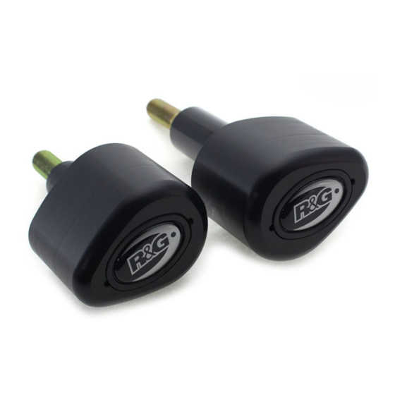
FITTING INSTRUCTIONS FOR CP0485
AERO CRASH PROTECTORS
DUCATI V2 2020-
T
.
HIS KIT CONTAINS THE ITEMS PICTURED AND LABELLED OVER PAGE
S
.
OME PARTS MAY BE SHOWN FOR CLARITY OF INSTRUCTIONS ONLY
D
.
O NOT PROCEED UNTIL YOU ARE SURE ALL PARTS ARE PRESENT
P
.
LEASE READ ALL INSTRUCTIONS BEFORE PROCEEDING
IF IN ANY DOUBT WHEN FITTING OUR PRODUCTS, CONSULT ONE OF OUR DEALERS
OR HAVE FITTED BY A QUALIFIED TECHNICIAN.
P
LEASE NOTE THAT THE WAY THE KIT IS PACKED DOES NOT NECESSARILY REPRESENT THE WAY OF
.
MOUNTING TO THE BIKE
I
,
N THE EVENT OF RUBBER WASHERS BEING USED TO HOLD COMPONENTS ONTO BOLTS
.
THESE RUBBER WASHERS CAN BE THROWN AWAY
DIGITAL COPIES OF THESE INSTRUCTIONS ARE AVAILABLE FROM:
WWW.RG-RACING.COM
R&G Racing
Unit 1, Shelley's Lane, East Worldham, Alton, Hampshire, GU34 3AQ
Tel: +44 (0)1420 89007 Fax: +44 (0)1420 87301
www.rg-racing.com
Email:
info@rg-racing.com
Advertisement

Related Manuals for R&G CP0485


Summary of Contents for R&G CP0485
- Page 1 Page 1 of 47 CP0485 FITTING INSTRUCTIONS FOR CP0485 AERO CRASH PROTECTORS DUCATI V2 2020- HIS KIT CONTAINS THE ITEMS PICTURED AND LABELLED OVER PAGE OME PARTS MAY BE SHOWN FOR CLARITY OF INSTRUCTIONS ONLY O NOT PROCEED UNTIL YOU ARE SURE ALL PARTS ARE PRESENT...
-
Page 2: Tools Required
Page 2 of 47 CP0485 TOOLS REQUIRED GENERAL TORQUE SETTINGS • Socket set to include 2.5, 3, 4, 5, 6, 7 & 8mm M4 BOLT = 8Nm A/F socket and wrench. M5 BOLT = • Torx head tools • Socket set to include a deep 8mm & 19mm M6 BOLT = socket and wrench. - Page 3 Page 3 of 47 CP0485 ITEM 20 M6 x 1.00 x 20mm BUTTON HEAD BOLT ITEM 21 M6 x 1.00 x 35mm BUTTON HEAD BOLT ITEM 22 M6 x 1.00 x 55mm BUTTON HEAD BOLT ITEM 23 M6 x 1.00 x 65mm BUTTON HEAD BOLT ITEM 24 M6 x 1.00 x 70mm LONG BUTTON HEAD BOLT...
- Page 4 Page 4 of 47 CP0485 RHS ASSEMBLY DIAGRAM 1 RHS ASSEMBLY DIAGRAM 2 R&G Racing Unit 1, Shelley’s Lane, East Worldham, Alton, Hampshire, GU34 3AQ Tel: +44 (0)1420 89007 Fax: +44 (0)1420 87301 www.rg-racing.com Email: info@rg-racing.com...
- Page 5 Page 5 of 47 CP0485 LHS ASSEMBLY DIAGRAM 1 FITTING PICTURES Picture 1 Picture 2 R&G Racing Unit 1, Shelley’s Lane, East Worldham, Alton, Hampshire, GU34 3AQ Tel: +44 (0)1420 89007 Fax: +44 (0)1420 87301 www.rg-racing.com Email: info@rg-racing.com...
- Page 6 Page 6 of 47 CP0485 Picture 3 Picture 4 Picture 5 Picture 6 Picture 7 Picture 8 R&G Racing Unit 1, Shelley’s Lane, East Worldham, Alton, Hampshire, GU34 3AQ Tel: +44 (0)1420 89007 Fax: +44 (0)1420 87301 www.rg-racing.com Email: info@rg-racing.com...
- Page 7 Page 7 of 47 CP0485 Picture 9 Picture 10 Picture 11 Picture 12 Picture 13 Picture 14 R&G Racing Unit 1, Shelley’s Lane, East Worldham, Alton, Hampshire, GU34 3AQ Tel: +44 (0)1420 89007 Fax: +44 (0)1420 87301 www.rg-racing.com Email: info@rg-racing.com...
- Page 8 Page 8 of 47 CP0485 Picture 15 Picture 16 Picture 17 Picture 18 Picture 19 Picture 20 R&G Racing Unit 1, Shelley’s Lane, East Worldham, Alton, Hampshire, GU34 3AQ Tel: +44 (0)1420 89007 Fax: +44 (0)1420 87301 www.rg-racing.com Email: info@rg-racing.com...
- Page 9 Page 9 of 47 CP0485 Picture 21 Picture 22 Picture 23 Picture 24 Picture 25 Picture 26 R&G Racing Unit 1, Shelley’s Lane, East Worldham, Alton, Hampshire, GU34 3AQ Tel: +44 (0)1420 89007 Fax: +44 (0)1420 87301 www.rg-racing.com Email: info@rg-racing.com...
- Page 10 Page 10 of 47 CP0485 Picture 27 Picture 28 Picture 29 Picture 30 Picture 31 Picture 32 R&G Racing Unit 1, Shelley’s Lane, East Worldham, Alton, Hampshire, GU34 3AQ Tel: +44 (0)1420 89007 Fax: +44 (0)1420 87301 www.rg-racing.com Email: info@rg-racing.com...
- Page 11 Page 11 of 47 CP0485 Picture 33 Picture 34 Picture 35 Picture 36 Picture 37 Picture 38 R&G Racing Unit 1, Shelley’s Lane, East Worldham, Alton, Hampshire, GU34 3AQ Tel: +44 (0)1420 89007 Fax: +44 (0)1420 87301 www.rg-racing.com Email: info@rg-racing.com...
- Page 12 Page 12 of 47 CP0485 Picture 39 Picture 40 Picture 41 Picture 42 Picture 43 Picture 44 R&G Racing Unit 1, Shelley’s Lane, East Worldham, Alton, Hampshire, GU34 3AQ Tel: +44 (0)1420 89007 Fax: +44 (0)1420 87301 www.rg-racing.com Email: info@rg-racing.com...
- Page 13 Page 13 of 47 CP0485 Picture 45 Picture 46 Picture 47 Picture 48 Picture 49 Picture 50 R&G Racing Unit 1, Shelley’s Lane, East Worldham, Alton, Hampshire, GU34 3AQ Tel: +44 (0)1420 89007 Fax: +44 (0)1420 87301 www.rg-racing.com Email: info@rg-racing.com...
- Page 14 Page 14 of 47 CP0485 Picture 51 Picture 52 Picture 53 Picture 54 Picture 55 Picture 56 R&G Racing Unit 1, Shelley’s Lane, East Worldham, Alton, Hampshire, GU34 3AQ Tel: +44 (0)1420 89007 Fax: +44 (0)1420 87301 www.rg-racing.com Email: info@rg-racing.com...
- Page 15 Page 15 of 47 CP0485 Picture 57 Picture 58 Picture 59 Picture 60 R&G Racing Unit 1, Shelley’s Lane, East Worldham, Alton, Hampshire, GU34 3AQ Tel: +44 (0)1420 89007 Fax: +44 (0)1420 87301 www.rg-racing.com Email: info@rg-racing.com...
-
Page 16: Fitting Instructions
Page 16 of 47 CP0485 FITTING INSTRUCTIONS PLEASE NOTE THAT BEFORE BEGINNING, YOU WILL NEED A SUITABLE STAND TO LIFT THE MOTORCYCLE ALLOWING REMOVAL OF THE REAR SHOCK. DO NOT PROCEED IF YOU ARE NOT COMFORTABLE TO DO THIS. HAVE FITTED BY A QUALIFIED TECHNICIAN. READ ALL STEPS BEFORE PROCEEDING. - Page 17 Page 17 of 47 CP0485 o Shift the whole fairing panel towards the rear of the bike to disengage the final pop pin at the top rear of the panel below the fuel tank, as shown in Picture 14. • Remove the RHS mid fairing inner panel, shown in picture 15: o Remove the locking nut from the engine stud at the base of the panel using an 8mm socket, arrowed in picture 16.
- Page 18 Page 18 of 47 CP0485 S0792 – 16.5mm long). Now fit one M6 washer (item 33), followed by the M6 nut (item 32) and then the remaining M6 washer (item 33), as shown in picture • Tighten the nut onto the bolt so that it just begins to tighten onto the plastic spacer.
- Page 19 Page 19 of 47 CP0485 The next steps will require removal of the LHS upper and mid fairing and entails similar process to the steps performed for the RHS fairing: • Remove the LHS inner nose panel (picture 8) by removing the following bolts: o 2 x pop rivets inside fairing surrounding radiator, removed by pressing the centre inwards to release and then removing plastic rivet.
- Page 20 Page 20 of 47 CP0485 • Take the left side mounting plate (Item 1 – M0382) and offer it up to the bike as shown in picture 48. Insert one M8 x 25mm long button head bolt (Item 18) through the front hole of the mounting plate and into the threaded boss on the side of the cylinder head, also shown in picture 48.
- Page 21 Page 21 of 47 CP0485 main mounting plate, as shown in picture 55, taking care to ensure the wiring runs above the spacer. o Tighten the bolt until you feel some compression from inside the protector using a 19mm socket and wrench, PLEASE NOTE THE CRASH...
- Page 22 Page 22 of 47 CP0485 PLEASE NOTE THE CRASH PROTECTOR MUST BE POSITIONED AS IN AERO- STYLE CRASH PROTECTOR ORIENTATION DIAGRAM ON PAGE 3, WITH BIGGER END TOWARD FRONT OF BIKE. o Turn a little more so that you feel the compression increase slightly. Then apply a quarter turn.
- Page 23 Page 23 of 47 CP0485 NOTICE DE MONTAGE POUR CP0485 PROTECTIONS CRASH DUCATI V2 2020- E KIT CONTIENT LES ARTICLES EN PHOTO ET ETIQUETTES SUR LA PAGE LES PARTIES PRESENTÉES PEUVENT ETRE UNIQUEMENT REPRESENTATIVES POUR LA CLARTE DES INSTRUCTIONS E PAS...
-
Page 24: Outils Requis
Page 24 of 47 CP0485 OUTILS REQUIS Valeurs de serrage M4 BOULON = 8Nm • Clé à cliquet + douilles 2.5, 3, 4, 5, 6, 7 & 8mm. M5 BOULON = 12Nm • Clés Torx M6 BOULON = 15Nm •... - Page 25 Page 25 of 47 CP0485 ARTICLE 19 M8 x 1.25 x 30mm BOULON ARTICLE 20 M6 x 1.00 x 20mm BOULON ARTICLE 21 M6 x 1.00 x 35mm BOULON ARTICLE 22 M6 x 1.00 x 55mm BOULON ARTICLE 23 M6 x 1.00 x 65mm BOULON ARTICLE 24 M6 x 1.00 x 70mm BOULON...
- Page 26 Page 26 of 47 CP0485 CÔTÉ DROIT SCHEMA 1 CÔTÉ DROIT SCHEMA 2 R&G Racing Unit 1, Shelley’s Lane, East Worldham, Alton, Hampshire, GU34 3AQ Tel: +44 (0)1420 89007 Fax: +44 (0)1420 87301 www.rg-racing.com Email: info@rg-racing.com...
- Page 27 Page 27 of 47 CP0485 CÔTÉ GAUCHE SCHEMA 1 R&G Racing Unit 1, Shelley’s Lane, East Worldham, Alton, Hampshire, GU34 3AQ Tel: +44 (0)1420 89007 Fax: +44 (0)1420 87301 www.rg-racing.com Email: info@rg-racing.com...
-
Page 28: Notice De Montage
Page 28 of 47 CP0485 NOTICE DE MONTAGE VEUILLEZ NOTER QU'AVANT DE COMMENCER, VOUS AUREZ BESOIN D'UN SUPPORT ADAPTÉ POUR LEVER LA MOTO AFIN D'ENLEVER L’AMORTISSEUR ARRIÈRE. NE PAS PROCÉDER SI VOUS N'ÊTES PAS A L’AISE À FAIRE CECI. FAIRE FAIRE LE MONTAGE PAR UN MECANICIEN QUALIFIÉ. - Page 29 Page 29 of 47 CP0485 À ce stade, le carénage peut être retiré et doit être soutenu à tout moment lors des prochaines étapes. o Retirez délicatement le carénage de la moto afin d'accéder aux 3 broches en plastique à l'intérieur du carénage et de les désengager des supports en caoutchouc, si nécessaire.
- Page 30 Page 30 of 47 CP0485 • Prendre les entretoises étagées simples (article 14 - S1252) et les insérer dans les trous arrière du guide de tuyau en plastique, comme indiqué sur la photo • Le guide de tuyau en plastique devrait maintenant se replacer, les deux entretoises étant alignées avec les trous de boulon dans le carter du moteur...
- Page 31 Page 31 of 47 CP0485 • Les quatre boulons de montage étant maintenant en place et les 2 plaques de montage correctement montées, serrez les boulons aux réglages de couple recommandés par le fabricant, comme indiqué sur la photo 38.
- Page 32 Page 32 of 47 CP0485 • Le panneau de montage du régulateur / redresseur doit être déplacé pour accéder au support de suspension supérieur : o Retirez 2 boulons à chapeau noir de 4 mm illustrés sur les photos 42 et •...
- Page 33 Page 33 of 47 CP0485 dans le petit trou de la plaque de renfort gauche (article 26 - MP0116) de sorte que le coude de la plaque sorte de la moto, comme indiqué sur les photos 52 et 53. Serrez-le sans bloquer, de sorte que le corset puisse encore être déplacé.
- Page 34 Page 34 of 47 CP0485 • La plaque de renfort doit maintenant être correctement positionnée comme indiqué sur la photo 58. • La protection crash côté gauche désormais être montée. En vous référant au schéma d'assemblage côté droit 2 et en suivant les étapes ci-dessous: o Prendre une des rondelles de 12 mm (article 9) et glisser sur le boulon à...
- Page 35 Page 35 of 47 CP0485 MONTAGEANLEITUNG FÜR CP0485 AERO STURZPADS DUCATI V2 2020- EILE SIND UNTEN ABGEBILDET UND GEKENNZEICHNET IE ABGEBILDETEN EILE DIENEN LEDIGLICH ZUR RKLÄRUNG Ü BERPRÜFEN IE ZUERST DASS ALLE EILE VORHANDEN SIND ESEN IE DIE ONTAGEANLEITUNG KOMPLETT DURCH...
- Page 36 Page 36 of 47 CP0485 SIE BENÖTIGEN FOLGENDES WERKZEUG ALLGEM. ANZUGSDREHMOMENT • Satz Steckschlüssel inkl. 2.5, 3, 4, 5, 6, 7 & M4 SCHRAUBE = 8Nm 8mm A/F Steckschlüssel M5 SCHRAUBE = • Torx-Schlüssel • Satz Steckschlüssel inkl. 8mm & 19mm M6 SCHRAUBE = Steckschlüssel und Schraubenschlüssel...
- Page 37 Page 37 of 47 CP0485 ARTIKEL 20 M6 x 1,00 x 20mm INBUSSCHRAUBE ARTIKEL 21 M6 x 1,00 x 35mm INBUSSCHRAUBE ARTIKEL 22 M6 x 1,00 x 55mm INBUSSCHRAUBE ARTIKEL 23 M6 x 1,00 x 65mm INBUSSCHRAUBE ARTIKEL 24 M6 x 1,00 x 70mm INBUSSCHRAUBE...
- Page 38 Page 38 of 47 CP0485 MOTORRAD VORNE RECHTE SEITE ZUSAMMENBAU - ZEICHNUNG 1 RECHTE SEITE ZUSAMMENBAU – ZEICHNUNG R&G Racing Unit 1, Shelley’s Lane, East Worldham, Alton, Hampshire, GU34 3AQ Tel: +44 (0)1420 89007 Fax: +44 (0)1420 87301 www.rg-racing.com Email:...
- Page 39 Page 39 of 47 CP0485 MOTORRAD VORNE LINKE SEITE ZUSAMMENBAU – ZEICHNUNG 1 R&G Racing Unit 1, Shelley’s Lane, East Worldham, Alton, Hampshire, GU34 3AQ Tel: +44 (0)1420 89007 Fax: +44 (0)1420 87301 www.rg-racing.com Email: info@rg-racing.com...
- Page 40 Page 40 of 47 CP0485 MONTAGEANLEITUNG WICHTIGER HINWEIS –SIE BENÖTIGEN EINEN GEEIGNETEN MONTAGESTÄNDER, UM DAS MOTORRAD AUFZUBOCKEN UND SOMIT DIE ENTFERNUNG DES HINTEREN STOSSDÄMPFERS ZU ERMÖGLICHEN. WENN SIE SICH DABEI UNSICHER SIND, BITTE EINEN UNSERER HÄNDLER KONTAKTIEREN ODER DAS KIT VON EINEM QUALIFIZIERTEN ZWEIRAD- MECHANIKER MONTIEREN LASSEN.
- Page 41 Page 41 of 47 CP0485 o 2 x 3mm Inbusschraube, obere hintere Verkleidung. o 1 x 3mm Inbusschraube versteckt hinter der mittleren Verkleidung – Zugang von hinten wie in Abbildung 13 abgebildet. Zum jetzigen Zeitpunkt kann die Verkleidung entfernt werden – sie sollte jedoch während der Ausführung der nächsten Schritte immer gestützt sein.
- Page 42 Page 42 of 47 CP0485 • Montieren Sie die ABS-Einheit aus Kunststoff wieder mit der original 3mm Inbusschraube. • Entfernen Sie die 2 x 8mm Wellenmuttern, die in Abbildung 29 mit Pfeilen gekennzeichnet sind, um das Verkleidungsteil des Bremsflüssigkeitsbehälters Motorrad...
- Page 43 Page 43 of 47 CP0485 • Entsprechend Zeichnung 2 – Zusammenbau für die rechte Seite, die vordere Montageplatte für die rechte Seite (Artikel 3 – M0384) in Position bringen – bitte darauf achten, dass die große Öffnung über den Gewindeeinsatz an der zuvor montierte Montageplatte passt, bevor Sie eine M6 x 65mm Inbusschraube (Artikel 23) in die obere Montageöffnung einsetzen, dann die...
- Page 44 Page 44 of 47 CP0485 o Die Verkleidung vorsichtig vom Motorrad aufhebeln, sodass die drei Kunststoffstifte innerhalb der Verkleidung zugänglich sind – diese von den Gummihalterungen lösen wie benötigt. VERSUCHEN SIE NICHT, DIE KOMPLETTE VERKLEIDUNG ZU ENTFERNEN. o Schieben Sie das komplette Verkleidungsteil nach hinten, um den letzten Stift oben am Verkleidungsteil hinten unter dem Tank zu lösen wie in...
- Page 45 Page 45 of 47 CP0485 • An der Montageplatte hinten, die M6 x 35mm Inbusschraube (Artikel 21) durch die Öffnung an der Platte, dann durch den kleinen Distanzhalter (Artikel 11 – S0670 – 9mm Länge) führen und im Motorgehäuse lose befestigen wie in Abbildung 50 abgebildet.
- Page 46 Page 46 of 47 CP0485 o BITTE DARAUF ACHTEN, DASS DAS STURZPAD WIE IN DER ZEICHNUNG STURZPAD AERO STYLE ORIENTIERUNG AUF SEITE 3 POSITIONIERT IST – DAS GRÖSSERE ENDE DES STURZPADS ZUM VORDERTEIL DES MOTORRADS GERICHTET o Noch etwas drehen, bis Sie merken, dass der Druck sich leicht erhöht, dann noch eine Vierteldrehung anwenden.
- Page 47 Page 47 of 47 CP0485 o Ziehen Sie die Schraube mittels eines 19 mm Steckschlüssels fest, bis Sie etwas Druck vom Inneren des Sturzpads spüren - BITTE DARAUF ACHTEN, DASS STURZPAD ZEICHNUNG STURZPAD AERO STYLE ORIENTIERUNG POSITIONIERT IST – DAS GRÖSSERE...
Need help?
Do you have a question about the CP0485 and is the answer not in the manual?
Questions and answers