Table of Contents
Advertisement
Quick Links
ISL70244SEHEV1Z
Evaluation Board
Introduction
The ISL70244SEHEV1Z evaluation platform is designed to
evaluate the ISL70244SEH. The ISL70244SEH contains two
high speed and low power op amps designed to take advantage
of its full dynamic input and output voltage range with rail-to-rail
operation. By offering low power, low offset voltage, and low
temperature drift coupled with its high bandwidth and
enhanced slew rates upwards of 50V/µs, these op amps make
it ideal for applications requiring both high DC accuracy and AC
performance. These amplifiers are designed to operate over a
single supply range of 2.7V to 40V or a split supply voltage
range of ±1.35V to ±20V. The ISL70244SEH is manufactured
in Intersil's PR40, silicon on insulator (SOI) process, which
makes this device immune to Single Event Latch-up and
provides excellent radiation tolerance. This makes it the ideal
choice for high reliability applications in harsh radiation-prone
environments.
Reference Documents
•
ISL70244SEH
Datasheet
• ISL70244SEH SMD
5962-13248
• ISL70244SEH Radiation Test Report
Evaluation Board Key Features
• Single Supply Operation: +3V to +40V
• Dual Supply Operation: +1.8V/-1.2V to ±20V
• Singled-Ended or Differential Input Operation
• External VREF Input
• Banana Jack Connectors for Power Supply and VREF Inputs
• BNC Connectors for Op Amp Input and Output Terminals
• Convenient PCB Pads for Op Amp Input/Output Impedance
loading.
Power Supplies
External power connections are made through the +V, -V, VREF
and Ground connections on the evaluation board. For single
supply operation, the -V and Ground pins are tied together to
the power supply negative terminal. For split supplies, +V and
-V terminals connect to their respective power supply
terminals. De-coupling capacitors C2, C3, C4 and C6 connect
to their respective supplies through R11 and R15 resistors.
These resistors are 100 but can be changed by the user to
provide additional power supply filtering, or to reduce the
voltage rate-of-rise to less than ±1V/µs. Two additional
capacitors, C5 and C7, are connected close to the part to filter
out high frequency noise. Anti-reverse diode D1 protects the
circuit in the momentary case of accidentally reversing the
power supplies to the evaluation board. The VREF pin can be
connected to ground to establish a ground referenced input for
split supply operation, or can be externally set to any reference
level for single supply operation.
AN1888 Rev.0.00
October 11, 2013
USER'S MANUAL
J5
J7
V-
J6
C2
C4
1µF
1µF
D1
C3
C6
0.1µF
0.1µF
C5
0.01µF
0.01µF
FIGURE 1. POWER SUPPLY CIRCUIT
Amplifier Configuration
A simplified schematic of the evaluation board is shown in
Figure 2. The input stage with the components supplied is
shown in Figure 3, with a closed loop gain of 10V/V. The
differential amplifier gain is expressed in Equation 1:
V
=
V
–
V
R
R
OUT
IN+
IN-
F
IN
For single-ended input with an inverting gain G = -10V/V, the
IN+ input is grounded and the signal is supplied to the IN-
input. VREF can be connected to a reference voltage between
the V+ and V- supply rails. For non-inverting operation with
G = 11V/V, the IN- input is grounded and the signal is supplied
to the IN+ input. The non-inverting gain is strongly dependent
on any resistance from IN- to GND. For good gain accuracy, a
0Ω resistor should be installed on the empty R5 pad. The VREF
pin must be connected to ground to establish a ground
referenced input for dual supply operation, or can be externally
set to any reference level for single supply operation. VREF
should not be left floating.
AN1888
Rev.0.00
October 11, 2013
V+
VREF
J8
J9
J10
C7
+
V
(EQ. 1)
REF
Page 1 of 6
Advertisement
Table of Contents

Related Manuals for Intersil ISL70244SEHEV1Z


Summary of Contents for Intersil ISL70244SEHEV1Z
-
Page 1: Evaluation Board
2.7V to 40V or a split supply voltage 0.1µF 0.1µF range of ±1.35V to ±20V. The ISL70244SEH is manufactured in Intersil’s PR40, silicon on insulator (SOI) process, which makes this device immune to Single Event Latch-up and 0.01µF 0.01µF provides excellent radiation tolerance. - Page 2 ISL70244SEHEV1Z ISL70244 (1/2) 100k IN - RIN- VOUT RIN+ IN + RREF+ VREF 100k VREF FIGURE 2. BASIC AMPLIFIER CONFIGURATION 100k OUTPUT FROM OUTPUT OPEN OPEN VREF 100k FIGURE 3. INPUT STAGE (1/2) FIGURE 4. OUTPUT STAGE (1/2)
- Page 3 ISL70244SEHEV1Z TABLE 1. ISL70244SEHEV1Z COMPONENTS PARTS LIST DEVICE # DESCRIPTION COMMENTS C2, C4 CAP, SMD, 1210, 1µF, 50V, 10%, X7R, ROHS Power Supply Decoupling C3, C6 CAP, SMD, 0805, 0.1µF, 50V, 10%, X7R, ROHS Power Supply Decoupling C5, C7 CAP, SMD, 0603, 0.01µF, 50V, 10%, X7R, ROHS...
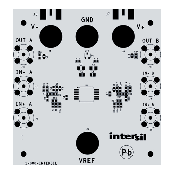
- Page 4 ISL70244SEHEV1Z FIGURE 5. ISL70244SEHEV1Z TOP VIEW AN1888 Rev.0.00 Page 4 of 6 October 11, 2013...
- Page 5 FIGURE 6. ISL70244SEHEV1Z SCHEMATIC DIAGRAM...
- Page 6 Notice Descriptions of circuits, software and other related information in this document are provided only to illustrate the operation of semiconductor products and application examples. You are fully responsible for the incorporation or any other use of the circuits, software, and information in the design of your product or system. Renesas Electronics disclaims any and all liability for any losses and damages incurred by you or third parties arising from the use of these circuits, software, or information.
Need help?
Do you have a question about the ISL70244SEHEV1Z and is the answer not in the manual?
Questions and answers