Emerson Rosemount Permasense WT210 Quick Start Manual
Wireless corrosion transmitter
Hide thumbs
Also See for Rosemount Permasense WT210:
- Quick start manual (24 pages) ,
- Quick start manual (16 pages) ,
- Quick start manual (20 pages)

Related Manuals for Emerson Rosemount Permasense WT210


Summary of Contents for Emerson Rosemount Permasense WT210
- Page 1 Quick Start Guide 00825-0100-4210, Rev BA December 2020 ™ Rosemount Wireless Permasense WT210 Corrosion Transmitter...
- Page 2 (I.S.) installations. Refer to the Rosemount Wireless Permasense Corrosion Transmitter Reference Manual for more instruction. The manual and this guide are also available electronically on Emerson.com\Rosemount. Shipping considerations Each device contains two “D” size primary lithium-thionyl chloride battery cells. Primary lithium batteries are regulated in transportation by the U.S.
-
Page 3: Table Of Contents
December 2020 Quick Start Guide Contents Overview............................5 Wireless considerations........................7 Field communicator connections....................8 Physical installation........................9 Commissioning device....................... 12 Additional hardware........................17 Product certifications......................... 20 Quick Start Guide... - Page 4 Quick Start Guide December 2020 Emerson.com/Rosemount...
-
Page 5: Overview
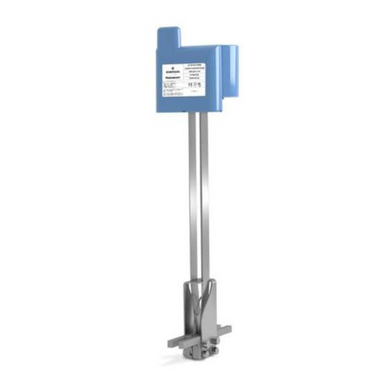
December 2020 Quick Start Guide Overview Figure 1-1: Rosemount Wireless Permasense WT210 Corrosion Transmitter A. Antenna B. Power module C. Head D. Waveguide E. Waveguide spacer F. Stabilizer G. Foot H. Thermocouple Quick Start Guide... - Page 6 • Stainless steel circular heat shield • M8 (compatible with 5/16-in. studs) Nord-Lock anti vibration washers, two per sensor • Lanyard kit, 316 stainless steel lanyard 6.5 ft. (2 m) in length, gripple No.2, release key Emerson.com/Rosemount...
-
Page 7: Wireless Considerations
Quick Start Guide Wireless considerations Power up sequence The Emerson Wireless Gateway should be installed and functioning properly before any wireless devices are powered. Commission the Rosemount Wireless Permasense WT210 and install the BP20E power module to power the device only after the gateway has been installed and functioning. This results in a simpler and faster network installation. -
Page 8: Field Communicator Connections
Rosemount BP20E power module. The USB connector is plugged in to the tablet PC as shown in Figure 3-1. Figure 3-1: IK220 Commissioning Kit A. Tablet PC B. CC21 C. USB cable plugged into USB port D. Rosemount Wireless Permasense WT210/ET210 sensor Emerson.com/Rosemount... -
Page 9: Physical Installation
December 2020 Quick Start Guide Physical installation The corrosion transmitter is connected directly to the piping being measured. Mounting considerations Procedure 1. When mounting sensors on pipe bends and elbows, studs must be aligned as follows a) Fit two nuts to the stud, the first at the top of the thread and the second 15-20 mm down the thread as shown in Figure 4-1. - Page 10 2. On straight pipes, ensure the studs are perpendicular to the sensor contact point. ® 3. Apply Loctite 8009 anti-seize compound to the threads. 4. Record the installation location, sensor ID, MAC address of the sensor, and power module serial number. Emerson.com/Rosemount...
- Page 11 December 2020 Quick Start Guide 5. Examine the thermocouple and make sure it is protruding past the end of the waveguide by about ⅛-in. (3 mm) so that it will press onto the pipe when the sensor is tightened as shown in Figure 4-3.
-
Page 12: Commissioning Device
Check the network ID of the gateway is visible in the network discovery list. Note Joining the device to the network could take several minutes. Figure 5-1: Rosemount WT210 Install Tool 5. In the Rosemount WT210 installation app software, select the Installation tab. Emerson.com/Rosemount... - Page 13 December 2020 Quick Start Guide CAUTION Overtightening Overtightening the nuts can damage the waveguides. Torque wrench setting value of 5 Nm (3.7 ft-lb) and ensure nuts are ONLY tightened incrementally as described below. 6. Tighten nuts ¼ turn at a time. a) Check the quality of the waveform with each turn as shown in Figure 5-2.
- Page 14 C. Plot of ultrasonic waveform (green) and the "envelope" of the signal (blue). Updated every 10 seconds. Click to pause the install; re-click to continue. D. Click to pause the sensor installation. E. Click to complete the sensor installation. It will then try to join its network. Emerson.com/Rosemount...
- Page 15 December 2020 Quick Start Guide Figure 5-3: Good Quality Waveform A. Surface wave B. 1st C. 2nd D. 3rd E. 4th Figure 5-4: Bad Quality Waveform A. Distorted surface wave B. Low amplitude Quick Start Guide...
- Page 16 3. Remove the CC21 and fit the power module. Note When the power module is fitted, the sensor will restart and try to ® join the WirelessHART gateway. In a large network of 100 sensors, this can often take two hours and sometimes up to six hours. Emerson.com/Rosemount...
-
Page 17: Additional Hardware
December 2020 Quick Start Guide Additional hardware Lanyard installation Procedure 1. Wrap the lanyard around the circumference of the pipe. The 6.6 ft. (2 m) length of lanyard will accommodate a maximum diameter of 20- in. (51 cm). When it is not possible to wrap the lanyard around a pipe, find an alternative attachment point for the lanyard. - Page 18 Figure 6-1 5. Feed the bare end of the lanyard into the return hole of the gripple. Adjust the gripple to minimize the slack in the lanyard cable between the attachment point and the sensor. Emerson.com/Rosemount...
- Page 19 December 2020 Quick Start Guide Figure 6-4: Gripple Installation Complete Note The wire can be released from the gripple using the release key. Figure 6-5: Wire Release A. Release key Quick Start Guide...
-
Page 20: Product Certifications
RF spectrum. Nearly every country requires this type of product certification. Emerson is working with governmental agencies around the world to supply fully compliant products and remove the risk of violating country directives or laws governing wireless device usage. - Page 21 December 2020 Quick Start Guide Standards: UL 913 - 8th Edition, Revision Dec 6 2013 Markings: CLASS I, DIV 1, GP ABCD, T4, T = -50 °C to +75 °C, IP67 Canada 7.7.1 I6 Canada Intrinsically Safe (IS) Certificate: SGSNA/17/SUW/00281 Standards: CAN/CSA C22.2 No.
- Page 22 ТР ТС 012/2011 Markings: 0Ex ia IIC T4 Ga X Specific Condition For Safe Use (X): See certificate for specific conditions of safe use. 7.13 India 7.13.1 India (PESO) Intrinsic Safety Certificate: A/P/HQ/MH/104/6454 (P474306) Markings: Ex ia IIC T4 Ga Emerson.com/Rosemount...
- Page 23 December 2020 Quick Start Guide Specific Conditions For Safe Use (X): See certificate for specific conditions of safe use. 7.14 Japan 7.14.1 I4 CML Intrinsically Safe (IS) Certificate: CML 17JPN2097X Standards: JNIOSH-TR-46-1:2015 JNIOSH-TR-46-6:2015 Markings: Ex ia IIC T4 Ga (-50 °C ≤ T ≤...
- Page 24 Quick Start Guide December 2020 7.16 Declaration of Conformity Figure 7-1: Declaration of Conformity Emerson.com/Rosemount...
- Page 25 December 2020 Quick Start Guide 7.17 China RoHS Quick Start Guide...
- Page 26 Quick Start Guide December 2020 Emerson.com/Rosemount...
- Page 27 December 2020 Quick Start Guide Quick Start Guide...
- Page 28 The Emerson logo is a Twitter.com/Rosemount_News trademark and service mark of Emerson Electric Facebook.com/Rosemount Co. Rosemount is a mark of one of the Emerson Youtube.com/user/ family of companies. All other marks are the RosemountMeasurement property of their respective owners.
Need help?
Do you have a question about the Rosemount Permasense WT210 and is the answer not in the manual?
Questions and answers