
Related Manuals for Hettich ZENTRIMIX 380 R


Summary of Contents for Hettich ZENTRIMIX 380 R
- Page 1 Operating manual ZENTRIMIX Translation of the original operating manual Read the instructions prior to performing any task! AB3200 Rev. 03 / 02.2021 1 / 88...
- Page 2 © 2017 Rev. 03 / 02.2021 Andreas Hettich GmbH & Co. KG Föhrenstraße 12 78532 Tuttlingen Germany +49 (0)7461 / 705-0 +49 (0)7461 / 705-1125 info@hettichlab.com service@hettichlab.com www.hettichlab.com 2 / 88 Rev. 03 / 02.2021 AB3200...
-
Page 3: Table Of Contents
Table of contents Table of contents Introduction......... . 1.1 Symbols. - Page 4 Table of contents 7.2 Centrifugation parameters......47 7.2.1 Temperature (t/°C)....... 7.2.2 Start-up and run-down parameters.
-
Page 5: Introduction
Introduction Introduction Symbols Signal words Signal word Meaning DANGER This combination of symbol and signal word indicates an immediate dangerous situation that will result in death or serious injury if it is not avoided. WARNING This combination of symbol and signal word indicates a possible dangerous sit- uation that can result in death or serious injury if it is not avoided. - Page 6 Introduction Symbols on the device Warnings/symbols on the device which are no longer rec- ognizable should be immediately replaced by the operating company. The images shown in the following depict the positions of the warnings and symbols affixed to the device. Fig.
- Page 7 Introduction Fig. 2: Warning stickers on the right outer side Attention, general danger point Nonobservance of this warning can lead to material damage and personal injury. Before using the device, make sure you read the operating instructions and observe the safety information. Symbol for separate collection of electric and electronic devices Symbol according to directive 2002/96/EC (WEEE).
-
Page 8: Symbol On The Shipping Carton Label
Introduction Symbol on the shipping carton label This way up. Shows the correct upright position of the package. Fragile, handle with care. Refers to a medical device that can break or be damaged if handled carelessly. temperature range The shipping packaging must be stored, transported and handled within the temperature range shown (-20°C - +60°C). -
Page 9: Intended Use
Introduction Interventions and modifications to devices by persons not authorized by the company Andreas Hettich GmbH & Co. KG will be at one's own risk and result in the voiding of all warranty claims, as well as the voiding of liability claims against Andreas Hettich GmbH &... -
Page 10: Replacement Parts/Consumable Material
For returns, please contact Hettich or the responsible Hettich sales partner. You will then receive a clearance cer- 10 / 88 Rev. 03 / 02.2021... - Page 11 Introduction tificate and return material authorization number. Devices without a signed clearance certificate will not be accepted in order to protect our employees. We ask for your understanding. AB3200 Rev. 03 / 02.2021 11 / 88...
-
Page 12: Safety Information
Safety information Safety information The device and its associated components and assemblies meet the currently valid safety standards individually and as a whole and meet the CE directives of the European Union. The device is safe if used as intended and observing the descriptions and information given in this documentation. - Page 13 Safety information Warning of premature pro- WARNING gram abort Warning of premature program abort! In the event of a premature program abort, such as a power failure, switching off during the program run or pulling out the mains plug, the desired effect on the samples might not be achieved.
- Page 14 Safety information Danger posed by selection of WARNING unsuitable parameters for dual Danger posed by selection of unsuitable parameters for dual centrifugation centrifugation! The maximum permissible speed (RPM) for ZentriMix appli- cations depends on the sample composition and sample container. Every ZentriMix sample container can only be used up to a certain rotational speed depending on the design and application;...
- Page 15 Safety information Danger due to hazardous sub- DANGER stances in the sample Danger due to hazardous substances in the sample No materials or material mixtures may be processed in a way which poses a risk of fire or explosion. − Therefore, thoroughly check the intended process regarding this hazard and take the appropriate measures to avoid personal injury.
- Page 16 Safety information Warning - Impermissible WARNING ambient temperature Warning - Impermissible ambient temperature! If the ambient temperature is outside of the permissible ambient temperature range for the samples, these might be compromised. − Observe the permissible maximum and minimum ambient temperatures for setting up the device. −...
- Page 17 Safety information Danger of infections due to DANGER improper disposal Danger of infections due to improper disposal! In the event of improper disposal of samples, there is a risk of injury to the user, disposal personnel and the environ- ment. −...
-
Page 18: Device Description
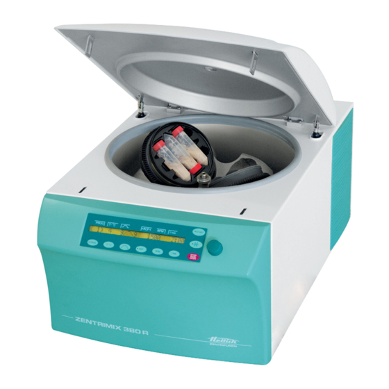
Device description Device description Further information about the control panel can be found in the Operation chapter ⮫ Chapter 6 ‘Operation’ on page 27. Fig. 4: Operating elements, front side Control panel Fig. 5: Device interior Centrifuging chamber Rotor cavity Fig. - Page 19 Device description Fig. 7: Rear side RS232 interface AB3200 Rev. 03 / 02.2021 19 / 88...
-
Page 20: Transport And Storage
Transport and storage Transport and storage Dimensions and weight with transport packaging ca.620 ca.925 Fig. 8: Transport packaging dimensions Data Value Unit Outer dimensions (L x W x H) 925 x 620 x Weight approx. 105 20 / 88 Rev. 03 / 02.2021 AB3200... - Page 21 Transport and storage Storage conditions WARNING Warning - Impermissible ambient temperature! If the ambient temperature is outside of the permissible ambient temperature range for the samples, these might be compromised. − Observe the permissible maximum and minimum ambient temperatures for setting up the device. −...
-
Page 22: Commissioning
Commissioning Commissioning ■ Set up and level the device at a suitable location so that it is stable. During setup, the required safety zone of 300 mm around the device must be complied with in acc. with IEC 61010-2-020 Ed.2 2006 "Safety requirements for electrical equipment for measurement, control, and lab- oratory use –... -
Page 23: Setting Up, Connecting And Switching On The Device
Commissioning WARNING Risk of injury due to parts falling out of the packaging! When parts fall out of the transport packaging, there is a risk of crushing injuries to extremities. − Observe the warnings for opening the packaging. − Only open the packaging at the specified point. Remove the packaging bands. - Page 24 Commissioning When lifting up the device, note the specified weight and only lift the device with a suitable number of helpers to avoid injuries. WARNING Warning - Position changed due to vibration The device might fall down if the set-up surface vibrates or if it is not flat or stable enough.
- Page 25 Commissioning Connecting the device Personnel: Authorized skilled personnel with special instruction ■ Make sure the operating voltage is correct, as speci- fied on the nameplate. Connect the mains cable included in delivery to the device plug on the device. Stick the other end in the socket. Fig.
- Page 26 Commissioning Fig. 12: Transport securing device Transport securing device NOTICE Before commissioning the device, remove the trans- port securing device from the interior. Remove the transport securing device. The device is now prepared for rotor installation. If ‘Enter max cycles = <30000>’ is displayed after switching on the device, the maximum permissible number of running cycles (specified on the rotor) must first be entered before the centrifugation run can be restarted.
-
Page 27: Operation
Operation Operation Operating elements START PROG T/°C t/min 4 9/;\9 1500 2:00 STOP PROG T/°C TIME OPEN Fig. 13: Control panel ‘Current program’ display segment ‘Temperature’ display segment ‘Start-up and run-down parameters’ display segment ‘Relative centrifugal force’ display segment ‘Speed’ display segment ‘Runtime’... - Page 28 Operation [TIME] key TIME ■ Runtime, parameter t/hms. h: hours. Can be set from 1 h to 99 h, in 1-hour increments. m: minutes. Can be set from 1 min to 59 min, in 1-minute increments. s: seconds. Can be set from 1 s to 59 s, in 1-second increments. ■...
- Page 29 Operation [Start-up and run-down parameters] key ■ Start-up levels, parameter _/ Level 9 = shortest start-up time, ... level 1 = longest start-up time. ■ Start-up time, parameter / t. Adjustable in 1-second increments. The adjustable time range depends on the set speed. It is only possible to set start-up times when these are activated Chapter 7.2.2 ‘Start-up and run-down parameters’...
- Page 30 Operation [PROG] key PROG ■ ‘RCL’ . Call up programs and program links, parameter Programs: Program locations 1 to 98 and PREC. Program links: Pro- gram locations A to Z. ■ ‘STO’ . Save programs and program links, parameter 99 programs can be saved (program locations 1 to 98 and PREC). The program location PREC (PRECOOLING) is reserved for the pre- cooling program.
-
Page 31: Opening The Lid
Operation Opening the lid Personnel: Authorized skilled personnel with special instruction ■ The lid can only be opened if the device is switched on and the rotor is stopped. If it is not possible to open the lid, actuate the emergency release ⮫ Chapter 6.8 ‘Emergency unlocking’... -
Page 32: Loading The Rotor
Operation Loading the rotor 6.5.1 Loading a rotor for classical centrifugation Standard centrifuge containers made of glass can be stressed up to RZB 4000 (DIN 58970 Part 2). ■ Check the rotor to make sure it is seated firmly. ■ For swing-out rotors, all rotor places must be occupied with the same hangers. -
Page 33: Loading A Rotor For Dual Centrifugation
■ Sample containers must be firmly sealed, even more strongly than required for other laboratory work, since they are shaken very vigorously upside-down. Only use containers approved by Hettich and do not exceed their maximum rotational speeds. ■ If not all positions of the adapter are used, the same numbers of sample containers must be distributed over the two adapters, whereby only one (mirrored) symmetrical arrangement may exist inside the adapter. -
Page 34: Handling Of Bio-Safety Systems
Operation 6.5.3 Handling of bio-safety systems Bio-safety systems may only be used when they are dry. Each time before using the bio-safety system, all parts of the bio-safety system must be visually inspected for damage. In addition, the sealing ring(s) of the bio-safety system must be checked to make sure they are in the cor- rect installation position. -
Page 35: Starting Centrifugation
Operation Starting centrifugation A centrifugation run can be aborted at any time by pressing the [STOP/OPEN] key. During a centrifugation run, parameters can be selected and changed ⮫ ‘Changing settings during the centrifugation run’ on page 44. The [RPM] and [RCF] buttons can be used to switch between the ‘RPM’... -
Page 36: Dual Centrifugation: Validating Application
Operation During the centrifugation run, the rotor speed or the RCF value, the temperature in the centrifuge chamber and the remaining time are displayed. Short-term centrifugation A short-time centrifugation is not possible if program link- ages are being used. The run-down is performed with the selected run-down parameters ⮫... - Page 37 Operation Required validation steps: ■ Evaluation of a potential hazard, such as the overheating of the sample or sample container, gas formation from the sample, breakage of the sample container due to mechanical, thermal or chemical overload. To do this, the device parameters are to be increased in small incre- ments in order to be able to notice potential hazards early enough.
-
Page 38: Emergency Unlocking
Operation NOTICE What to do in the event of unbalance The ZentriMix is equipped with an unbalance switch like every commercially available laboratory centrifuge. If strong vibrations should result from incorrect loading or process-intrinsic operations which the unbalance switch still tolerates, but still leads to increased wear, the process must [STOP/OPEN] key twice. -
Page 39: Removing And Installing The Rotor
Operation Insert the Allen key (included in delivery as an accessory) horizontally into the emergency release opening on the front side and carefully rotate by one-half turn in the clockwise direction until the lid can be opened. �� The lid releases and springs open slightly. Remove the Allen key from the opening. - Page 40 Operation Carefully remove the rotor upward and out of the device. �� The interior (centrifuge chamber) is now accessible. NOTICE If the rotor is incorrectly installed or fastened, it could end up coming loose. When installing the rotor, make sure that the driver of the rotor shaft is sitting correctly in the rotor groove.
-
Page 41: Cooling
Operation Place the adapter (in the case of rotor for dual centrifugation) into the rotor cavities. Put the device into operation. Fig. 22: Rotor cavity symmetrically arranged 6.10 Cooling The temperature can be set from -20 °C to +40 °C / -4 °F to +104 °F. -
Page 42: Software Description
Software description Software description All settings and queries are carried out via the keyboard. The corresponding menus are selected by pressing keys or key combinations. Program settings Centrifugation parameters *** Machine Menu *** Fig. 23: Main menu After switching on the device, the start screen appears. Here, the display changes between the product type of the device, the software version and, depending on the setting, the last loaded program or program location no. - Page 43 Software description If parameters are changed, the program location number is displayed in parentheses ‘( )’. This means that the centrifu- gation data on the display no longer agrees with the stored centrifugation data of the program location. * The display of program links is only possible if the ‘Multi programs’...
-
Page 44: Calling Up/Loading Program (Rcl 1-99)
Software description ‘+’ or ‘-’ using the [adjusting knob] . ‘+’ Program is write-protected ‘-’ Program is not write-protected. Press the [START] key to save the setting. PROG T/°C t/min 5 20 9/;\9 1500 2:00 Changing settings during the It is not possible to change the settings during the centrifu- centrifugation run gation run if program links are used. -
Page 45: Calling Up/Loading A Program Link (Rcl A-Z)
Software description [PROG] key until STO 1 is displayed. Press the PROG T/°C t/min STO 1 [adjusting knob] to set the desired program location. Use the PROG T/°C t/min STO 5 If a ‘+’ is displayed after the program location, the data is write-protected. -
Page 46: Editing A Program Link (Edit A-Z)
Software description 7.1.4 Editing a program link (EDIT A-Z) It is possible to save 25 program linkages (program loca- tions A to Z; there is no program location J). A program linkage can consist of no more than 20 programs. The speed adjustment from one program to the next one is always done in a program linkage with the start-up param- eter of the next program. -
Page 47: Saving A Program Link (Sto A-Z)
Software description 7.1.5 Saving a program link (STO A-Z) In order to save the current program link (e.g. as a copy), proceed as fol- PROG T/°C t/min 19 9/;\9 > 63< 2:00 lows: [PROG] key until ‘STO A’ is displayed. Press the PROG T/°C... -
Page 48: Temperature (T/°C)
Software description 7.2.1 Temperature (t/°C) The temperature can only be set for devices with a cooling unit. The temperature can be input in degrees Celsius (°C) or degrees Fahrenheit (°F). Setting the temperature unit ⮫ Chapter 7.3.5.4 ‘Temp Unit’ on page 63. If degrees Fahrenheit (°F) is set as the tem- perature unit, the letter ‘F’... - Page 49 Software description [adjusting knob] . Set the start-up level with the PROG T/°C t/min _/; = t=00:00:11 [TIME] key. Press the PROG T/°C t/min _/t = 00:11 Indicates which start-up level corresponds to the set start-up time. Set the start-up time with the [adjusting knob] .
-
Page 50: Rcf And Rad
Software description [START] key. To accept the settings, press the PROG T/°C t/min (1) 20 9/;\9 1500 2:00 Chapter 7.1.2 ‘Save programs (STO 1-99)’ Save the program ⮫ on page 44 . 7.2.3 RCF and RAD The relative centrifugal force (RCF) depends on the centri- fuging radius (RAD). -
Page 51: Speed (Rpm)
Software description It is only possible to query the integral RCF if the display of the integral RCF is activated. ⮫ Chapter 7.3.5.6 ‘RCF Inte- gral’ on page 64. The integral RCF is not saved. The integral RCF is deleted after starting the next centrifugation run or after switching off the device. -
Page 52: Runtime (T/Hms)
Software description If in doubt you should obtain clarification from the manufacturer. PROG T/°C t/min If the speed in the activated program is higher than the N > ROTOR MAX maximum rotor speed (Nmax), no centrifugation run can be started. ‘N > ROTOR MAX’ is displayed ⮫ Chapter 9 ‘Trou- bleshooting’... - Page 53 Software description Chapter 7.1.2 ‘Save programs (STO 1-99)’ Save the program ⮫ on page 44 . Start of runtime timer The start of the runtime timer can only be set if the ‘Dual time mode’ function is activated ⮫ Chapter 7.3.5.12 ‘Dual time mode’...
-
Page 54: Precooling Of The Rotor
Software description [START] key to start the run. Press the PROG T/°C t/min (1) 20 9/;\9 1500 00:00 [START] key flashes until the rotor is read in; then �� The LED in the ‘00:00’ . the LED is illuminated. The timer begins at [STOP/OPEN] key to end the centrifugation run. -
Page 55: Machine Menu
Software description Machine Menu ‘Machine Menu’ . General device settings can be made in the ‘Machine Menu’ , proceed as follows: To call up the * By entering a PIN, only the program lock (LOCK) can be altered, but none of the other setting options. Fig. -
Page 56: Change Pin
Software description ‘Machine Menu �� Change LOCK’ ⮫ Further Change to the menu PROG T/°C t/min information on page 55 . -] Change LOCK [START] key. Press the PROG T/°C t/min LOCK = 3 �� The lock status is displayed. ‘LOCK = <3>... - Page 57 Software description [RCF] key Only the 100s place of the PIN will be changed. [RPM] key Only the 10s place of the PIN will be changed. If an incorrect PIN was set, then ‘old PIN = ---- <START>’ is displayed. In this case, set the valid PIN with the [adjusting knob] and then press [START].
-
Page 58: Info
55 . -] Info [START] key. Press the PROG T/°C t/min Zentrimix 380 R �� The device model is displayed. [PROG] key. Press the PROG T/°C t/min Mains Voltage : 230V �� The mains voltage is displayed. -
Page 59: Operating Time
Software description [PROG] key. Press the PROG T/°C t/min SW-Version = V 01.19 �� The program version of the device is displayed. [PROG] key. Press the PROG T/°C t/min FC-SW-Version = 9 �� The program version of the frequency converter is displayed. [STOP/OPEN] key Press 1x ⇒... - Page 60 Software description [STOP/OPEN] key Press 1x ⇒ Back to the menu ‘Machine Menu’ . [STOP/OPEN] key Press 1x ⇒ Back to the main display Cycle counter It is only appropriate to use the cycle counter if the same set of hangers is always worked with. The cycle counter is activated by setting the maximum per- missible cycles.
-
Page 61: Settings
Software description [START] key to save the setting. Press the PROG T/°C t/min Store max cycles... Resetting the cycle counter to 0 / entering maximum permis- sible number of running cycles ‘0’ as follows, or the maximum permis- The cycle counter can be reset to sible number of running cycles can be entered. - Page 62 Software description The acoustic signal can be activated or deactivated as follows: ‘Machine Menu �� Settings’ ⮫ Chapter 7.3 Change to the menu PROG T/°C t/min ‘Machine Menu’ on page 55 . -] Settings [PROG] key until the ‘Sound/Bell’ parameter is displayed. Press the PROG T/°C...
- Page 63 Software description 7.3.5.3 Start program Start program After switching on, the centrifugation data of program 1 or the last used program/program link is displayed. To set what centrifugation data is to be displayed at switch-on, proceed as follows: ‘Machine Menu �� Settings’ ⮫ Chapter 7.3 Change to the menu PROG T/°C...
- Page 64 Software description 7.3.5.5 Ramp Unit Please observe the notice ⮫ Further information on page 55 Activate/deactivate the start-up and run-down times as follows: ‘Machine Menu �� Settings’ ⮫ Chapter 7.3 Change to the menu PROG T/°C t/min ‘Machine Menu’ on page 55 . -] Settings [PROG] key until the ‘Ramp Unit’...
- Page 65 Software description 7.3.5.8 Multi programs Please observe the notice ⮫ Further information on page 55 The program link can be activated or deactivated as follows: ‘Machine Menu �� Settings’ ⮫ Chapter 7.3 Change to the menu PROG T/°C t/min ‘Machine Menu’ on page 55 . -] Settings [PROG] key until the ‘Multi programs’...
- Page 66 Software description ‘Machine Menu �� Settings’ ⮫ Further informa- Change to the menu PROG T/°C t/min tion on page 55 . -] Settings [PROG] key until the ‘Cool acc time’ parameter is displayed. Press the PROG T/°C t/min Cool acc time = 15 s [adjusting knob] to set the desired value.
- Page 67 Software description ‘Dual time mode’ function can be activated or deactivated as follows: ‘Machine Menu �� Settings’ ⮫ Further informa- Change to the menu PROG T/°C t/min tion on page 55 . -] Settings [PROG] key until the ‘Dual time mode’ parameter is dis- Press the PROG T/°C...
-
Page 68: Cleaning, Disinfection And Maintenance
Cleaning, disinfection and maintenance Cleaning, disinfection and maintenance DANGER Danger due to insufficient cleaning! In the case of insufficient cleaning or non-observance of the cleaning regulations, there is a risk of contamination for the user. − Observe the specified cleaning regulations. −... -
Page 69: Disinfection
Cleaning, disinfection and maintenance NOTICE To clean the device, use a mixture of anionic and non-ionic surfactants in an aqueous, multivalent alcohol base, which generate a nearly neutral (pH 7 +/-) concentrate. Do not use any cleaning agents for cleaning, such as caustic alkalis, peroxides, chlorine compounds, acids or bases. -
Page 70: Maintenance
Cleaning, disinfection and maintenance NOTICE To disinfect the centrifuge, use a suitable aldehyde-free dis- infectant with an ethanol base (at least 45%) with the fol- lowing efficacy spectrum: − bactericidal (incl. MRSA) − tuberculocidal − yeasticidal (C. albicans) − virus-inactivating (HBV, HIV, HCV, Vaccinia, BVDV, influ- enza/Noro viruses) When using the disinfectant, observe the safety data sheet from the disinfectant manufacturer. - Page 71 Check by a service technician from the manufacturer. Service technician In the case of swing-out rotors, the lifting lugs must be greased regularly (Hettich lubricating grease no. 4051), to ensure the hangers swing out evenly. To grease the lifting lugs, proceed as follows: Check whether the lifting lugs have an adequate film of grease.
-
Page 72: Troubleshooting
Troubleshooting Troubleshooting If the error can't be remedied using the troubleshooting table, notify Customer Service. Please specify the type of device and the serial number. Both numbers can be found on the name plate of the device. Fault description Cause Remedy No display Device switch switched off. - Page 73 Troubleshooting Fault description Cause Remedy CONTROL-ERROR 22, 25.1– Error, defective electronics. Perform a MAINS-RESET 25.4; SER I/O - ERROR 31, Chapter 9.1 ‘Performing a mains ⮫ reset’ on page 74 . If the error persists 34, 36; ° C * - ERROR 51, 53 –...
-
Page 74: Performing A Mains Reset
Troubleshooting Fault description Cause Remedy N > ROTOR MAX The rotor was changed. The Set a speed (up to the maximum installed rotor has a higher max- speed of the previously used rotor). [START] key to detect the imum speed than the previously Press the used rotor, and it has not yet rotor. -
Page 75: Technical Data
Technical data Technical data Model ZENTRIMIX 380 R Manufacturer Andreas Hettich GmbH & Co. KG, D-78532 Tuttlingen Type 3200 3200-01 Mains voltage (± 10%) 200-240 V 1~ 110 – 127 V 1~ Mains frequency 50 – 60 Hz 60 Hz... -
Page 76: Type Plate
Technical data Dimensions Width 472 mm 472 mm depth 759 mm 769 mm Height 418 mm 418 mm Weight approx. 81,5 kg approx. 89 kg 10.1 Type plate Fig. 32: Type plate Manufacturer logo EAC mark, CE mark Country of manufacture Year of manufacture Mains supply frequency Kinetic energy... -
Page 77: Dimensions
Technical data 10.2 Dimensions 706.28 Fig. 33: Dimensions AB3200 Rev. 03 / 02.2021 77 / 88... -
Page 78: Disposal
Disposal Disposal Before disposal, the device must be decontaminated and cleaned to pro- tect people, the environment and property. Before disposing of the device, the respective legal regulations must be observed. According to the directive 2012/19/EU , devices may no longer be dis- posed of in the household waste. -
Page 79: Declaration Of Conformity And List Of Standards
Declaration of conformity and list of standards Declaration of conformity Valid standards and regula- Hettich centrifuges and incubators are high-tech products. They are subject tions to extensive testing and certification processes according to the following standards and regulations in their respectively valid version:... - Page 80 Declaration of conformity and list of standards ■ IEC 61010-1 Ed.2 2001 "Safety requirements for electrical equipment for measurement, control, and laboratory use – Part 1: General require- ments" (contamination level 2, overvoltage category II) ■ IEC 61010-2-010 Ed.2 2003 "Safety requirements for electrical equip- ment for measurement, control, and laboratory use –...
- Page 81 Declaration of conformity and list of standards Environmental management system according to (valid for the manufacture of all products) ■ EN ISO 14001:2004 + COR 1: 2009 "Environmental management sys- tems - Requirements with guidance for use" AB3200 Rev. 03 / 02.2021 81 / 88...
-
Page 82: Glossary
Glossary Glossary Dual centrifugation In dual centrifugation, one or more sample containers is centrifuged, each of which rotates additionally about another axis. This special kind of centri- fugation leads to a fundamentally different result than classical centrifuga- tion. While classical centrifugation is a separation method, dual centrifugation is a method for mixing, homogenizing or dispersion. -
Page 83: Index
Index Index Acoustic signal......61, 62 Get HELP # no......57 Activating or deactivating program linkage. - Page 84 Index Programs and program links Short-term centrifugation....36 Overview......42 Signal after ending the centrifugation run.
-
Page 85: 15 Appendix
15 Appendix... -
Page 86: A Rotors And Accessories
Rotors and accessories Rotors and accessories Rotor Hangers Insert/adapter Radius [mm] 3205 3211 3221-A 3236 3206 3211 3218 3221-A 3236 3234 1752 1738 1761 125 / 171 1762-A 1763-A 1764 1765 1766 1767 1768 1769 1771-A 1772-A 1773 1774-A 1775 1777 1778 1779... - Page 87 Rotors and accessories Rotor Hangers Insert/adapter Radius [mm] 3235 Tab. 1: Centrifuging radius Hanger + lid 1752 + 1751 Tab. 2: Bio-safety systems Rotor Hanger/insert/adapter Bio-seal 3205 3211 3221-A 3236 3206 3211 3218 3221-A 3236 3234 1752 1751 Tab. 3: Bio-seal Rotor Maximum number of running Period of use [years]...
- Page 88 Rotors and accessories Rotor Hanger/insert/ Speed _/^9 (97%) ^\_9 [sec] Temperature adapter [°C] [sec] 3205 3211 2500 3221-A 3236 3206 3211 1500 3218 3221-A 3236 3234 1752 5000 Tab. 5: Start-up and run-down time, lowest reachable temperature in the centrifuge chamber Lowest reachable temperature at maximum speed, 1 h running time and 20°C room temperature Hanger/insert/adapter...
Need help?
Do you have a question about the ZENTRIMIX 380 R and is the answer not in the manual?
Questions and answers