Hettich EBA 270 Repair Instructions
Hide thumbs
Also See for EBA 270:
- Operating instructions manual (66 pages) ,
- Operating instructions manual (21 pages)
Table of Contents
Advertisement
Advertisement
Table of Contents

Related Manuals for Hettich EBA 270


Summary of Contents for Hettich EBA 270
- Page 1 EBA 270 Repair instructions 2011 Andreas Hettich GmbH & Co. KG AR2300EN...
- Page 2 (07461) 705-0 (07461) 705-125 info@hettichlab.com, service@hettichlab.com www.hettichlab.com © 2011 by Andreas Hettich GmbH & Co. KG All rights reserved. No part of this publication may be reproduced without the prior written permission of the copyright owner. Modifications reserved! AR2300EN / 2011...
-
Page 3: Table Of Contents
Contents Introduction ........................5 Symbol meanings ......................5 Description of the centrifuge ................... 6 Control panel (A2) ....................6 Electronics (A1) ....................... 7 Motor (M1) ....................... 7 Speed sensor (B1)....................7 Lid lock (A4)......................8 Imbalance switch (S1) ..................... 8 Troubleshooting procedures ................... - Page 4 Technical documents....................26 10.1 Block diagram of the control ..................26 10.2 Connecting diagrams .....................27 10.2.1 Abbreviations of the cable colours ..............27 10.2.2 Connecting diagram EBA 270................28 10.3 Technical specifications ..................29 4/29...
-
Page 5: Introduction
In such an event any guarantee claim or liability claim against the Andreas Hettich GmbH & Co. KG company expire. • Only original spare parts and original accessories licensed by the Andreas Hettich GmbH & Co. KG company are allowed to be utilised. -
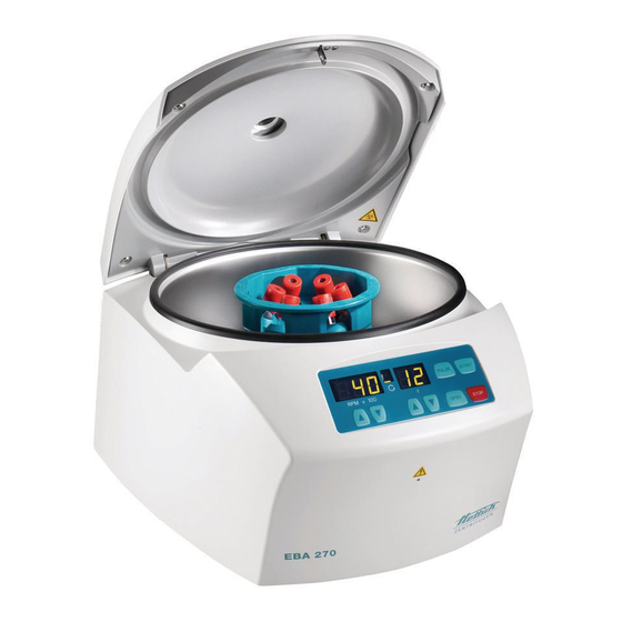
Page 6: Description Of The Centrifuge
Description of the centrifuge This microprocessor controlled centrifuge mainly consists of the following components: • Control panel (A2) • Electronics (A1) • Motor (M1) with speed sensor (B1) • Lid lock system (A4) • Imbalance switch (S1) All electronic components are on mains, due to the DC-coupling. Control panel (A2) The control panel (A2) have only restricted control tasks, it disposes of the following characteristics:... -
Page 7: Electronics (A1)
Electronics (A1) The electronics (A1) is a combination of: • Control panel • Voltage supply • Frequency converter The electronics (A1) carries out the following tasks: • Power supply 15 V, DC for imbalance switch (S1) and speed sensor (B1) •... -
Page 8: Lid Lock (A4)
Lid lock (A4) • The lid can be opened only if the electronics (A1) has detected rotor standstill. • After pressing the key the magnet at the lid lock is energized for a short time OPEN and the lid opens. •... -
Page 9: Error Messages
Error messages The error messages will be indicated in the speed display of the control panel. e.g. : PULSE START RPM x 100 OPEN STOP Perform a MAINS RESET • Switch off the mains switch (switch position "0"). • Wait at least 10 seconds and then switch on the mains switch again (switch position "Ι"). -
Page 10: Description And Elimination Of Errors
Description and elimination of errors – 1 – Tacho error Speedometer pulses break down during the centrifugation run. The rotor slows down without braking until it stops. No further user operation possible. • Reset error code: Wait 2 minutes until the safety time is passed and the rotation indicator has stopped to turn. - Page 11 – 3 – Imbalance Imbalance on the motor axle. The rotor slows down braked until it stops. After the rotor is at standstill the lid can be opened. • Reset error code: Open the lid or perform a MAINS RESET. •...
- Page 12 – 6 – Overvoltage Overvoltage The rotor slows down without braking until it stops. No further user operation possible. • Reset error code: Perform a MAINS RESET. • Mains voltage is too high. Admissible mains voltage see chapter 10.3, pg. 29. •...
- Page 13 – 9 – Overtemperature Overtemperature in the motor. Temperature > 125°C / 257°F. The rotor slows down without braking until it stops. No further user operation possible. • Reset error code: Perform a MAINS RESET. • Motor is defective. Temperature in the motor is higher than 125°C / 257°F. •...
-
Page 14: Defects Without Error Indications
– d – Lid lock error The microswitch at the lid lock has opened during the centrifugation run. The rotor slows down without braking until it stops. No further user operation possible. • Reset error code: Perform a MAINS RESET. •... - Page 15 The lid can not be opened The lid can not be opened. With the closed lid the symbol " " (lid open) illuminates in the rotation indicator . • Open the lid by using the emergency release. • Microswitch at the lid lock (A4) is defective or has loose contact on plug.
-
Page 16: Settings And Enquiries
Control panels supplied as spare part are not yet set to machine version C (EBA 270). It is important to set the machine version C. The machine version C (EBA 270) must be set as follows: 1. Set the machine version C by using the... -
Page 17: Enquiry The Programme Versions
Enquiry the programme versions 1. Switch off the mains switch. 2. Keep the key beneath the speed indicator and the key pressed PULSE simultaneously. 3. Switch on the mains switch and release the keys again. 4. Press the key beneath the speed indicator so often until the programme version of the control panel (e.g. -
Page 18: Imbalance Switch-Off
Imbalance switch-off The imbalance switch-off is specified by the indication of the difference in weight of opposite rotor positions. When having a difference in weight within the range of 4 g to 6 g during run-up, the drive has to switch off before reaching a speed of 2000 RPM. The imbalance switch-off is adjusted by changing the distance of the imbalance switch. -
Page 19: Functional Check After A Repair
Functional check after a repair After a repair a functional check of the unit must be carried out. For functional check a test run with the loaded rotor must be performed. During the test run the followings must be checked: •... -
Page 20: General Arrangement Of The Components
General arrangement of the components Item Designation Housing Leg spring Sealing ring Centrifuge chamber Motor cover Motor Speed sensor Rubber-metal bearing Upper anti-twist device Lower anti-twist device Imbalance switch Lid lock complete Appliance plug (without fuse holder) Fuse holder Fuse Electronics (230V version) Electronics (120V version) Control panel... - Page 21 Outer sight-glass and gluing ring 1,000 PC. E1323 9000 VP.06.300.158 Labels "scratched out waste container" 1,000 PC. E3010 150 104.00.15.00 Imbalance switch kpl. EBA 270 1,000 ST E3358 20 102.85.92.01 Control panel - LED 1,000 ST E1422 60 905.55.06.56 Ribbon cable 170mm/4-conductor...
- Page 22 17/18 Fig. 2 21/29...
-
Page 23: Assembling And Disassembling Components
Assembling and disassembling components Before mounting and removing components the mains switch must be switched off and the centrifuge must be disconnected from the mains supply. Removing the centrifuge chamber • Open the lid. • Switch off the mains switch and disconnect the centrifuge from the mains supply. -
Page 24: Motor (M1) / Rubber-Metal Bearings / Speed Sensor (B1)
Motor (M1) / Rubber-metal bearings / Speed sensor (B1) Wait at least 2 minutes after disconnecting the centrifuge from the mains, until the intermediate circuit capacitors of the frequency converter are unloaded. • Remove the centrifuge chamber as described in chapter 9.1, pg. 22. •... -
Page 25: Electronics (A1)
Electronics (A1) Wait at least 2 minutes after disconnecting the centrifuge from the mains, until the intermediate circuit capacitors of the frequency converter are unloaded. • Remove the centrifuge chamber as described in chapter 9.1, pg. 22. • Pull all plugs on the electronics (pg. 21, Fig. 2, item 17/18), see pg. 27, chapter 10.2. •... -
Page 26: Imbalance Switch (S1)
Imbalance switch (S1) • Remove the centrifuge chamber as described in chapter 9.1, pg. 22. • Pull the plug S603 on the electronics (A1), see pg. 27, chapter 10.2. • Remove the fixations at the imbalance switch cable. • Unscrew the two fastening screws (pg. 21, Fig. 2, m) of the imbalance switch (pg. 21, Fig. -
Page 27: 10 Technical Documents
10 Technical documents 10.1 Block diagram of the control Steuerteil (A2) / Control panel (A2) Prozessor / Processor EEPROM Serielle Schnittstelle Serial interface S601 Netzeingang S102L Mains input Gerätestecker (A3) S102N Appliance plug (A3) Deckelverriegelung (A4) S104 Lid lock (A4) Elektronik (A1) Unwuchtschalter (S1) S603... -
Page 28: Connecting Diagrams
10.2 Connecting diagrams 10.2.1 Abbreviations of the cable colours Abbreviation Colour black brown blue gold green GNYE green-yellow grey orange pink silver turquoise Transp. transparent violet white yellow 27/29... -
Page 29: Connecting Diagram Eba 270
10.2.2 Connecting diagram EBA 270 28/29... -
Page 30: Technical Specifications
10.3 Technical specifications Andreas Hettich GmbH & Co. KG Manufacturer D-78532 Tuttlingen Model EBA 270 Type 2300 2300-01 Mains voltage (± 10%) 200 - 240 V 1∼ 100 - 127 V 1∼ Mains frequency 50 - 60 Hz 50 - 60 Hz...
Need help?
Do you have a question about the EBA 270 and is the answer not in the manual?
Questions and answers