Notifier ID50 Operating Manual
Hide thumbs
Also See for ID50:
- Installation, comissioning & configuration manual (94 pages) ,
- Operating manual (56 pages) ,
- Installation, commissioning & configuration manual (94 pages)
Table of Contents
Advertisement
Quick Links
Advertisement
Table of Contents

Related Manuals for Notifier ID50


Summary of Contents for Notifier ID50
- Page 1 ID50/60 operating manual 997-264, Issue 4 September 2002...
-
Page 3: Table Of Contents
ID50 Series Panel - Operating Manual Contents Introduction Associated Documents The ID50 / ID60 Series Panel Cleaning Panel Controls and Indicators Controls Indicators Automatic Alarms - What to do Fire Fault Plant Alarm Operator Actions at Panel Introduction RESET Pushbutton... - Page 4 ID50 Series Panel - Operating Manual DISABLE / ENABLE - User Option 4.10 CLOCK - User Option 4.11 VIEW MODE - User Option 4.12 Commissioning Appendix 1 - Log Book A1-1 Appendix 2 - Maintenance A2-1 Appendix 3 - ID60 Single Loop Panel...
- Page 5 ID50 Series Panel - Operating Manual ID50 Series Panel 997-264, Issue 4 September 2002...
-
Page 7: Introduction
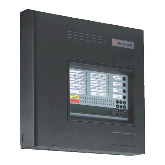
Introduction Appendix 3 1.1 Associated Documents ID50 Series Panel - Installation, Commissioning Configuration Manual (Ref. 997-263-XXX) 1.2 The ID50 / ID60 Series Panel... -
Page 8: Cleaning
1.2.1 Device Type Abbreviations Abbreviation Type Description Note: ID60 Panel 1.3 Cleaning Do not... -
Page 9: Panel Controls And Indicators
Panel Controls and Indicators 2.1 Controls Function Pushbuttons • Section 4.2 • Section 4.3 • Section 4.4 • Section 4.5 Numeric/Cursor Keys • Section 4.6 Keyswitch Section 4.1.3 Section 4.1.4... -
Page 10: Indicators
2.2 Indicators Zone Status LED Indicators • • Panel/System LED Indicators • • Visible/Audible Indicators • Section 4.1.1 • Section 4.1.2... -
Page 11: Automatic Alarms - What To Do
Automatic Alarms - What to do Only one alarm condition can be displayed at a time on the LCD 3.1 Fire Automatic panel actions: DISPLAYED LOGGED TIME OF LOGGED DEVICE ZONE ALARM ALARM ALARM CONDITION TYPE NUMBER CONDITIONS CONDITION ALARM FIRE 02 / 05 11:59... - Page 12 Recommended operator actions: Note: Status: NORMAL Sat 01/12/2001 00:00:00 Section 4.1.1 Liquid crystal Display...
- Page 13 3.1.1 Fire in Delayed Mode Note: EN54-2: 7.11 (c) Total time for configured delays MUST NOT the TOTAL exceed 600 seconds. time for both periods is 600 secs Note: Status: NORMAL Sat 01/12/2001 00:00:00...
-
Page 14: Fault
3.2 Fault Automatic panel actions: Recommended operator actions: FAULT 01 / 03 14:55 NO REPLY FROM DEVICE > FAULT 01 / 03 Z01 : M12 14:55 < - - - Zone Text - - - > < - - - Device Text - - - > Note: Note: FAULT... - Page 15 FAULT 01 / 03 14:55 For Service Contact ***** ****** Note: Status: NORMAL Sat 01/12/2001 00:00:00 3.2.1 Power Fail If both the AC and Battery power fail, the indicators and LCD are non-operational FAULT 01 / 02 14:55 NO MAINS SUPPLY FAULT 01 / 02 14:55...
-
Page 16: Plant Alarm
3.3 Plant Alarm PLANT 01 / 01 14:55 < - - - Zone Text - - - > < - - - Device Text - - - > Status: NORMAL Sat 01/12/2001 00:00:00... -
Page 17: Operator Actions At Panel
Operator Actions at Panel 4.1 Introduction except when the keyswitch remains turned to the right 0..9... - Page 18 Operations within this manual require Level 2 access (code or keyswitch), although a Level 3 access code may be entered Throughout this manual a U accompanied by a number represents a Level 2 access code 0..9...
-
Page 19: Reset Pushbutton
4.2 RESET Pushbutton 4.3 MUTE BUZZER Pushbutton... -
Page 20: Silence/Resound Pushbutton
4.4 SILENCE / RESOUND Pushbutton... -
Page 21: End Delays/Evacuate Pushbutton
4.5 END DELAYS / EVACUATE Pushbutton... -
Page 22: Numeric Keys
4.6 Numeric Keys 0..9 0..9 0..9 It is possible to press and hold the ‘ ’ (Shift) 0..9 pushbutton while entering numbers... -
Page 23: Level 2 Option Menus
4.7 Level 2 Option Menus... -
Page 24: Test - User Option
4.8 TEST - User Option Extinguishing System - Testing SLC device outputs. - Page 25 × ×...
- Page 26 × × × ×...
- Page 27 × × × ×...
- Page 28 ×...
- Page 29 × × ×...
- Page 30 × The standard function of the control keys is suppressed while this test is active. Normal function resumes upon test completion. × ×...
-
Page 31: Disable / Enable - User Option
4.9 DISABLE / ENABLE - User Option... - Page 32 × × ×...
- Page 33 ×...
- Page 34 4.9.2 Outputs - User Option [U0 Disable/Enable] 1:Zone 2:Outputs 3:Day Mode 4:Delays [U0 Disable/Enable] 1:Sounders 2:Ext. Systems 3:Others Disable ALL Sounder Outputs Press 3to confirm <:Cancel Disable ALL Extinguishant System Outputs Press 3to confirm <:Cancel Disable ALL Relay and CTL Outputs Press 3to confirm <:Cancel [U0 Disable/Enable]...
- Page 35 ID50 Series Panel - Operating Manual 4.9.3 Day Mode - User Option If Day Mode is enabled during panel commissioning, this option allows the user to activate/deactivate Day Mode delays during the set Day Mode time period. This has no effect on any sensor sensitivity changes that may have been configured during commissioning.
- Page 36 4.9.4 Delays - User Option 997-263 ID50 Series Panel Installation, Commissioning and Configuration Manual, Sections 5.5.3 Primary/Extend Delay Timers 5.7.8 CBE Zones [U0 Disable/Enable] 1:Zone 2:Outputs 3:Day Mode 4:Delays Disable Delays Press 3to confirm <:Cancel [U0 Disable/Enable] 1:Zone 2:Outputs 3:Day Mode...
-
Page 37: Clock - User Option
4.10 Clock - User Option ACCESS TO MENUS RESTRICTED Enter Level 2/3 Passcode: ..< : BackSp Note: [U0] 1 : Test 2 : Disable/Enable 3 : Clock 4 : View Mode 5 : Commission [U0 Clock] 1 : Time 2 : Date... - Page 38 4.10.1 Time - User Option [U0 Clock] 1 : Time 2 : Date ENTER NEW TIME (format hh : mm) - - : - - <:Cancel ENTER NEW TIME (format hh : mm) 19 : 11 <:Cancel [U0 Clock] 1 : Time 2 : Date Note: ENTER NEW TIME (format hh : mm)
- Page 39 4.10.2 Date - User Option [U0 Clock] 1 : Time 2 : Date ENTER NEW DATE (format dd/mm/yy) - -/- -/- - <:Cancel ENTER NEW DATE (format dd/mm/yy) 12/12/00 <:Cancel [U0 Clock] 1 : Time 2 : Date Note: ENTER NEW DATE (format dd/mm/yy) 22/22/22 <:Cancel Invalid Value Entered !
-
Page 40: View Mode - User Option
4.11 View Mode - User Option ACCESS TO MENUS RESTRICTED Enter Level 2/3 Passcode: ..< : BackSp Note: [U0] 1 : Test 2 : Disable/Enable 3 : Clock 4 : View Mode 5 : Commission [U0 View] 1:Log 2:Devices 3:Faults 4:Input Events... - Page 41 4.11.1 Log - User Option [U0 View] 1:Log 2:Devices 3:Faults 4:Input Events 5:Disabled × : More [LOG 001/512] 12/12/00 11:48 CPU FAULT > [LOG 002/512] 12/12/00 14:55 DEVICE ADDED > [LOG 002/512] 12/12/00 14:55 ZONE10 > Note:...
- Page 42 4.11.2 Devices - User Option [U0 View] 1:Log 2:Devices 3:Faults 4:Input Events 5:Disabled × : More [U0 Sensor 01] Type OPT Level 050% PW1:286 2:283 3:285 4:1003 5:0292 <:Exit Note: [U0 Sensor 02] Type OPT Level 050% PW1:286 2:283 3:285 4:1003 5:0292 <:Exit [U0 Sensor 03]...
- Page 43 4.11.3 Faults - User Option [U0 View] 1:Log 2:Devices 3:Faults 4:Input Events 5:Disabled × : More Note: FAULT 01 / 03 14:55 NO REPLY FROM DEVICE > FAULT 01 / 03 14:55 NO REPLY FROM DEVICE > FAULT 01 / 03 M12 MCP 14:55 <...
- Page 44 4.11.4 Input Events - User Option [U0 View] 1:Log 2:Devices 3:Faults 4:Input Events 5:Disabled × : More PLANT 01 / 10 M12 AUX 14:55 < - - - Zone Text - - - > < - - - Device Text - - - > The system has NO warnings present <:Exit PLANT...
- Page 45 4.11.5 Disabled - User Option [U0 View] 1:Log 2:Devices 3:Faults 4:Input Events 5:Disabled × : More DISABLEMENT 01 / 01 Z01 S02 TMP < - - - Zone Text - - - > < - - - Device Text - - - > There are no loop devices disabled <:Exit DISABLEMENT...
- Page 46 4.11.7 Voltages - User Option [U0 View] 6:Alarm Count 7:Voltages 8:Versions × : More [U0 VOLTS] BATTERY VOLTS = 27.0 × : Select <:Cancel [U0 ANALOGUE] EARTH = 271 × : Select <:Cancel [U0 ANALOGUE] SOUNDER 1 = 164 × : Select <:Cancel [U0 ANALOGUE] SOUNDER 2 = 164 × : Select <:Cancel [U0 ANALOGUE] SOUNDER 3 = 164...
-
Page 47: Commissioning
4.11.8 Version - User Option [U0 View] 6:Alarm Count 7:Voltages 8:Versions × : More [U0 VERSION] System : nnn-nnn-nnn n.nn Loop : nnn-nnn n.nn 4.12 Commissioning 997-263, ID50 Series Panel - Installation, Commissioning & Configuration Manual, Sections 4 and 5... -
Page 49: Appendix 1 - Log Book A1-1
ID50 Series Panel - Operating Manual Appendix 1 - Log Book In accordance with EN54 part 14, it is the user’s responsibility to maintain a log book and to record all events resulting from or affecting the system. The log book should be kept in a place accessible to authorised persons (preferably near the control panel). - Page 50 ID50 Series Panel - Operating Manual Event Data Date Time Event Action Required Date Completed Initials 997-264, Issue 4 A1 - 2 September 2002...
- Page 51 ID50 Series Panel - Operating Manual Event Data Date Time Event Action Required Date Completed Initials A1 - 3 997-264, Issue 4 September 2002...
- Page 52 ID50 Series Panel - Operating Manual Event Data Date Time Event Action Required Date Completed Initials 997-264, Issue 4 A1 - 4 September 2002...
- Page 53 ID50 Series Panel - Operating Manual Appendix 2 - Maintenance Create a log book (see Appendix 1) in accordance with the recommendations of EN54 Part 14. This log book should be used and maintained for recording events as described below. A2.1 Routine Testing In order to ensure that the system is fully operational, and to comply with the requirements of EN54 Part 14...
- Page 55 ID50 Series Panel - Operating Manual Appendix 3 ID60 Single Loop Panel Differences The ID60 Panel differs from the ID50 Panel in that it supports Very Intelligent Early Warning (VIEW ) sensors. This appendix describes differences to the user operations required by the ID60 Panel.
- Page 56 Charles Avenue T: +44 (0) 1444 230 300 Burgess Hill F: +44 (0) 1444 230 888 W. Sussex E: sales@notifier.ltd.uk RH15 9UF www.notifier.ltd.uk local distributor Quality Systems Certificate No. 154 Assessed to ISO9001 Every care has been taken in the preparation of this document but no liability can be accepted for the use of the information therein. Design features may be changed or amended without prior notice.
Need help?
Do you have a question about the ID50 and is the answer not in the manual?
Questions and answers