Advertisement
Use
CC1N7817en
24.02.2015
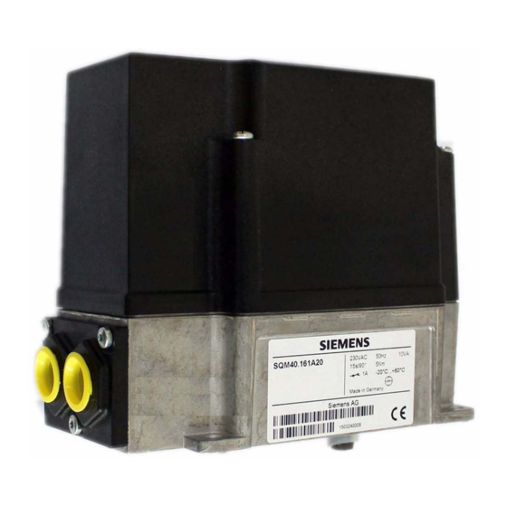
Actuator SQM40.../SQM41...
Actuators for air and gas
dampers
Electromotoric actuator up to 18 Nm torque
Clockwise and counterclockwise variants
Running times from 5 up to 65 seconds
Different shaft ends available
Electronic version with analog control input
Internal position indication
Drive shaft can be disengaged
Variants with UL and CSA approval, as well as GL marine approval
The SQM40.../SQM41... and this Data Sheet are intended for use by OEMs which
integrate the actuators in their products!
The SQM40.../SQM41... actuators are suited for driving oil pressure controller, butterfly
valves, dampers or for use on other applications that require rotary motion.
Areas of application are oil and gas burners of medium to higher capacity as well as
thermal process plants.
The actuators are used primarily for load-dependent control of the flow of gas, oil and
combustion air:
In connection with 3-position or modulating controllers (e.g. 4...20 mA), and/or ...
... directly by burner controls
SQM40...
SQM41...
Building Technologies Division
7
817
Advertisement
Table of Contents

Related Manuals for Siemens SQM40 Series


Summary of Contents for Siemens SQM40 Series
- Page 1 Actuator SQM40.../SQM41... SQM40... Actuators for air and gas SQM41... dampers Electromotoric actuator up to 18 Nm torque Clockwise and counterclockwise variants Running times from 5 up to 65 seconds Different shaft ends available Electronic version with analog control input ...
- Page 2 The user must ensure that the actuators meet the requirements of the relevant application standards Safety-related applications are only available with Siemens burner controls! All product-related activities (mounting, settings and maintenance) must be performed by qualified and authorized personnel Caution! ...
-
Page 3: Mounting Notes
Mounting notes Ensure that the relevant national safety regulations and notes on standards are complied with In geographical areas where DIN regulations apply, the mounting and installation requirements of VDE must be satisfied, especially DIN/VDE 0100, 0550 and DIN/VDE 0722 ... -
Page 4: Electrical Connection
Electrical connection The actuators must always be powered via a prefuse of max. 6.3 AT (as per DIN EN 6012- 2/5) For the protective earth connection, the housing of all variants has a marked PE connecting terminal. A tightening torque of 1.2 Nm must be observed for fitting the screw ... -
Page 5: Standards And Certificates
Cam settings The mechanical setting facility for the cams is physically separated from the connection terminals. When the actuator is disconnected from power, the switches can be adjusted via a scale. The cams can be changed via adjusting screws. The scale indicates the angles of the switching points. -
Page 6: Mechanical Design
Mechanical design Housing Lower housing part made of die-cast aluminum Housing cover made of impact-proof and heat-resistant plastic Drive motor Synchronous motor Coupling Shaft can be manually disengaged from the motor by operating the coupling (coupling pin (K1)) ... - Page 7 Type summary (other types on request) Regional Operating Potentio- Direction of version voltage meter rotation Product no. 2.5Nm/5s SQM40.025A21 *) 2.5Nm/5s SQM40.065A23 *) **) 5Nm/15s SQM40.115R11 **) ...
- Page 8 Type summary (other types on request) (cont’d) Regional Operating Potentio- Direction version voltage meter of rotation Product no. 10Nm/30s SQM40.261A20 10Nm/30s SQM40.261A21 10Nm/30s SQM40.261R11 10Nm/30s ...
- Page 9 Type summary (cont´d) (other types on request) (cont’d) Regional Operating Potentio- Direction version voltage meter of rotation Product no. 5Nm/15s SQM41.141A21 5Nm/15s SQM41.144R11 5Nm/15s SQM41.145A21 5Nm/15s ...
-
Page 10: Drive Shafts
Type summary (cont´d) (other types on request) (cont’d) Note Not all types of actuators are available ex stock. Additional versions are available on request. Drive shafts: Max. Shaft Type of drive shaft torque 10 mm, woodruff key as per DIN 6888 10 Nm 15 Nm ... -
Page 11: Mounting Plate
Accessories Accessories must be ordered as separate items: Mounting plate ASK33.1 For mounting the SQM40... / SQM41... onto the VKP... proportional controlling element See Mounting Instruction 74 319 0843 0 (M7646) Mounting kit ASK33.4 For fitting SQM40... / SQM41... to the butterfly valve VKF41.xxC See Mounting Instruction 74 319 0916 0 (M7813 / 7814) Front cover (on request) For making the connections for the power supply lines... -
Page 12: Technical Data
Technical Data General unit data Operating voltage - SQM4x.xxxA1… AC 120 V -15%/+10% - SQM4x.xxxA2… AC 230 V -15%/+10% - SQM4x.xxxR1… AC 120 V -15%/+10% Operating frequency 50…60 Hz ±6% Drive motor Synchronous motor Power consumption 10 VA Operating angle Between 0°... - Page 13 Technical Data (cont´d) Lifetime 250,000 start cycles (close open close) under load with the rated torque in the entire rotation angle range. 2,000,000 control cycles under load with 75% of rated torque in rotation angle range of 10° Analog inputs General Linearity...
- Page 14 Technical Data (cont´d) 2*1000 double potentiometer with Conductive plastic Resistance potentiometer separated resistance tracks Operating voltage DC 10 V Permissible hysteresis 0.3% of 90° or of 135°, depending on type Total resistance tolerance ±20% Effective angular rotation 90° or 135°, depending on type Terminal strip Triple-pole For cross-sectional areas of...
- Page 15 Connection diagrams and connection terminals SQM4x.x1xxxx Electronic version Mains voltage terminals Dimensioning X1-1 2...10 V Input max. DC 10 V to X1-5 X1-2 4...20 mA Input max. 20 mA to X1-5 0...135 1 X1-3 Input 0-135? 0...135 2 X1-4 Input 0...135 ...
-
Page 16: Range Adjustment
Connection diagrams and connection terminals (cont’d) SQM4x.x2xxxx Electronic version, only for types with 5 seconds running time Low-voltage terminals Dimensioning X1-1 4...20 mA Input max. 20 mA to X1-2 X1-2 Input Mains voltage terminals Dimensioning X2-1 Open position reached (I) Output AC 120 V / AC 230 V max. - Page 17 Connection diagrams and connection terminals (cont’d) SQM4x.x3xxxx 2-position version with 2 end switches and 2 auxiliary switches, 3 relays Mains voltage terminals Dimensioning X1-1 Free X1-2 Controller, open Input AC 120 V / AC 230 V max. 1 A, cos >0.9 X1-3 Controller release Input...
-
Page 18: Electronic Version
Connection diagrams and connection terminals (cont’d) SQM4x.x4xxxx Electronic version Low-voltage terminals Dimensioning X1-1 2...10 V Input max. DC 10 V to X1-2 X1-2 Input X1-3 4...20 mA Input Max. 20 mA to X1-2 0...135 1 X1-4 Input 0-135? 0...135 2 X1-5 Input 0...135 ... - Page 19 Connection diagrams and connection terminals (cont’d) Max. potentiometer (high-fire) 90° / 135° Max. Min. 0° Min. potentiometer (low-fire) 7817z08e/0315 Note! When starting up, the direction of rotation of the potentiometer setting must be observed: 90° / 135° Max. Min. 0°...
- Page 20 Connection diagrams and connection terminals (cont’d) SQM4x.x5xxxx Electronic version Low-voltage terminals Dimensioning X1-1 4...20 mA Input max. 20 mA to X1-2 X1-2 Input Mains voltage terminals Dimensioning X2-1 Open position reached (I) Output AC 120 V / AC 230 V max.
- Page 21 Connection diagrams and connection terminals (cont’d) 3-position version with 2 end switches and 4 auxiliary switches SQM4x.x6xxxx Mains voltage terminals Dimensioning X1-1 Move to ignition position Input AC 120 V / AC 230 V (III) max. 1 A, cos >0.9 X1-2 Auxiliary switch AUX (IV) Output...
- Page 22 Connection diagrams and connection terminals (cont’d) 2-position version with 2 end switches and 3 auxiliary switches, 1 relay SQM4x.x7xxxx Mains voltage terminals Dimensioning X1-1 Move to ignition position Input AC 120 V / AC 230 V (III) max. 1 A, cos >0.9 X1-2 Auxiliary switch AUX (IV) Output...
- Page 23 Connection diagrams and connection terminals (cont’d) 3 position version with 2 end switches and 4 auxiliary switches SQM4x.x8xxxx Mains voltage terminals Dimensioning X1-1 Move to position (III) Input AC 120 V / AC 230 V max. 1 A, cos >0.9 X1-2 Auxiliary switch AUX (IV) Output...
- Page 24 Position indication, preadjustment and coloring of the cams Position indication SQM40... Position indication SQM41... External angle scale Internal angle scale Marking in slot shape Arrow marking Pay attention to markings! Note! The setting of the switch positions must be checked before startup. Electronic version SQM4x.x1xxxx SQM4x.x4xxxx...
- Page 25 Position indication, preadjustment and coloring of the cams (cont’d) 3 position version SQM4x.x6xxxx SQM4x.x8xxxx Color Position Preadjustment Cam I High-fire 90° Cam II Blue OFF / low-fire 0° Cam III Orange Ignition position 15° Cam IV Yellow 30° Auxiliary switch Cam V Black 30°...
- Page 26 Slot for woodruff key SQM4x.xx1xxx 3x3.7 series A Din6888 SQM4x.xx4xxx Square SQM4x.xx5xxx D-shaft SQM4x.xx7xxx Slot for parallel key A5x3x28 DIN6885 T3 7817m01e/0312 2015 Siemens AG Building Technologies Division, Berliner Ring 23, D-76437 Rastatt Subject to change! 26/26 Building Technologies Division CC1N7817en 24.02.2015...
Need help?
Do you have a question about the SQM40 Series and is the answer not in the manual?
Questions and answers