Siemens SQM5 Series Operation
Reversing actuator with analog input signal
Hide thumbs
Also See for SQM5 Series:
- Technical instructions (31 pages) ,
- Technical instructions (28 pages) ,
- Technical instructions (31 pages)
Table of Contents
Advertisement
Quick Links
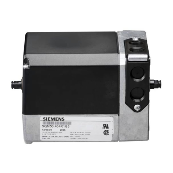
SQM5... Reversing Actuator with Analog Input Signal
Product Description
Reversing actuator used to position flow control
valves, butterfly valves, dampers, or any application
requiring rotary motion with an analog input signal.
Product Numbers
SQM5x.xxxRxGx for 4 to 20 mA input signal
SQM5x.xxxRxHx for 0 to 135 ohm input signal
SQM5x.xxxRxKx for 0 to 10 Vdc input signal
Actuator Torque:
SQM50.2...
90 in/lb
SQM50.3...
90 in/lb
SQM50.4...
140 in/lb
SQM53.4...
200 in/lb
SQM56.5...
310 in/lb
SQM56.6...
400 in/lb
SQM... motors allow torque on either end of the
AGA58.3 and AGA58.4 shafts.
NOTE:
For detailed information, see Technical
Instructions 155-517P25.
Caution Notations
CAUTION:
Equipment damage may occur
if procedures are not followed
as specified.
Installation
Cover Removal
Use a Phillips screwdriver to loosen the two screws
on the actuator cover corners. See Figure 1.
Lift the screws and raise the cover. See Figure 2.
Item Number 129-400, Rev. CA
Max Shaft Torque:
AGA58.1
200 in/lb
AGA58.3
220 in/lb
AGA58.4
270 in/lb
AGA58.7
400 in/lb
Installation Instructions
Figure 1.
Rotational Direction Verification
Actuator model numbers that end with "R" are
factory configured for clockwise (cw), minimum to
maximum rotation when facing the gear end of the
actuator, or counterclockwise (ccw) rotation when
facing the other end of the actuator. The gear end of
the actuator is the side opposite of the visual
position indicator.
Actuator Mounting
SQM5... actuators can be mounted in any
orientation. Optional base mounting brackets are
available.
SQM5... actuators can also be face-mounted using
self-tapping screws in combination with the various
holes on the face of the actuator gear end.
Switch Adjustment
SQM5...actuators are factory-wired with Switch I
(maximum), Switch II (fully closed/economy position)
and Switch III (minimum/low-fire). The individual
switch cams I, II, and III are factory set to 90°, 0°
and 10°, respectively. See Figures 3 and 4.
Document No. 129-400
October 2, 2009
Figure 2.
Page 1 of 5
Advertisement
Table of Contents

Related Manuals for Siemens SQM5 Series


Summary of Contents for Siemens SQM5 Series
- Page 1 Installation Instructions Document No. 129-400 October 2, 2009 SQM5… Reversing Actuator with Analog Input Signal Product Description Reversing actuator used to position flow control valves, butterfly valves, dampers, or any application requiring rotary motion with an analog input signal. Product Numbers SQM5x.xxxRxGx for 4 to 20 mA input signal SQM5x.xxxRxHx for 0 to 135 ohm input signal SQM5x.xxxRxKx for 0 to 10 Vdc input signal...
- Page 2 After pressing the shaft release button in and slightly upward, the shaft can be manually rotated. After the shaft has been manually Page 2 of 5 Siemens Industry, Inc.
- Page 3 Disconnect the circuit board wire marked 51 single-phase power supply. during high voltage testing. Reconnect it to the grounding terminal after the test. Figure 4. Basic Functional Diagram of AGA56.4… Figure 5. AGA56.41/42/43… Terminal and Trim Potentiometer Boards. Siemens Industry, Inc. Page 3 of 5...
- Page 4 I Under no circumstances should and III, then the switch cam settings terminals A and Z be powered at the determine the modulating range same time. Actuator damage will occur. (See Figure 6). Page 4 of 5 Siemens Industry, Inc.
- Page 5 Information in this publication is based on current specifications. The company reserves the right to make changes in specifications and models as design improvements are introduced. Product or company names mentioned herein may be the trademarks of their respective owners. © 2009 Siemens Industry, Inc. Siemens Industry, Inc.
Need help?
Do you have a question about the SQM5 Series and is the answer not in the manual?
Questions and answers