Table of Contents
Advertisement
Quick Links
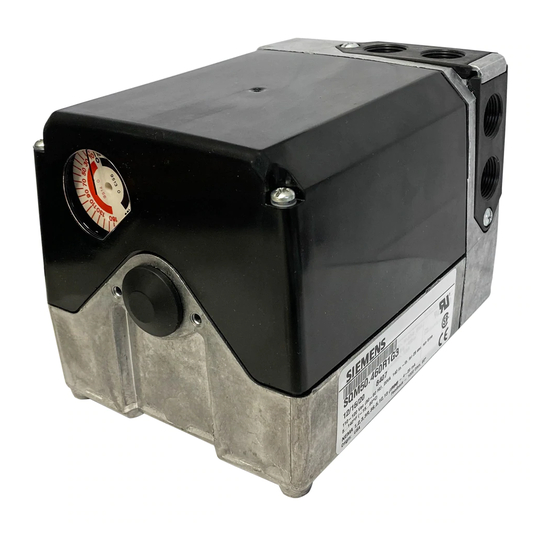
SQM5... Reversing Actuators, with Multiple Analog Control Input
Signals
Product Description
Reversing actuator used to position flow control
valves, butterfly valves, dampers, or any application
requiring rotary motion with multiple analog input
signals.
Product Numbers
SQM5x.xxxRxZx for 4 to 20 mA, 0 to 135 ohm and
0 to 10 Vdc input signals
Actuator Torque:
SQM50.2...
90 in/lb
SQM50.3...
90 in/lb
SQM50.4...
140 in/lb
SQM53.4...
200 in/lb
SQM56.5...
310 in/lb
SQM56.6...
400 in/lb
SQM... motors allow torque on either end of the
AGA58.3 and AGA58.4 shafts.
NOTE: For detailed information, see Technical
Instructions (155-517P25).
Caution Notations
CAUTION:
Installation
Cover Removal
Use a Phillips screwdriver to loosen the two screws
on the actuator cover corners. See Figure 1.
Lift the screws and raise the cover. See Figure 2.
Item Number 129-401, Rev. DA
Max Shaft Torque:
AGA58.1
200 in/lb
AGA58.3
220 in/lb
AGA58.4
270 in/lb
AGA58.7
400 in/lb
Equipment damage may occur
if you do not follow the
procedures as specified.
Installation Instructions
Figure 1.
Rotational Direction Verification
Actuator model numbers that end with "R" are
factory configured for clockwise (cw), minimum to
maximum rotation when facing the gear end of the
actuator, or counterclockwise (ccw) rotation when
facing the other end of the actuator. The gear end of
the actuator is the side opposite of the visual
position indicator.
Actuator Mounting
SQM5... actuators can be mounted in any
orientation. Optional base mounting brackets are
available.
SQM5... actuators can also be face mounted using
self-tapping screws in combination with the various
holes on the face of the actuator gear end.
Switch Adjustment
SQM5...actuators are factory-wired with Switch I
(maximum), Switch II (fully closed/economy position)
and Switch III (minimum/low-fire). The individual
switch cams I, II, and III are factory set to 90°, 0°
and 10°, respectively. See Figures 3 and 4.
Document No. 129-401
January 18, 2008
Figure 2.
Page 1 of 6
Advertisement
Table of Contents

Related Manuals for Siemens SQM50 series


Summary of Contents for Siemens SQM50 series
- Page 1 Installation Instructions Document No. 129-401 January 18, 2008 SQM5… Reversing Actuators, with Multiple Analog Control Input Signals Product Description Reversing actuator used to position flow control valves, butterfly valves, dampers, or any application requiring rotary motion with multiple analog input signals.
- Page 2 After pressing the shaft release button in and slightly upward, the shaft can Page 2 of 6 Siemens Building Technologies, Inc.
- Page 3 0...10 V AUTO shown in auto position actuator switch common Maximum/High fire "Economy"/Fully closed Minimum/Low fire Auxilliary IV...VI ASZ... (1000 Ohm) 21 12 wire leads Figure 4. Basic Functional Diagram of AGA56.9… Siemens Building Technologies, Inc. Page 3 of 6...
- Page 4 Once the maximum position is reached, terminal 11 operation. (on switch I) will be energized to provide position feedback. 7. Connect power to terminal ZL to drive the actuator to the minimum (low-fire) position. Once the minimum Page 4 of 6 Siemens Building Technologies, Inc.
- Page 5 U4 and Y0.) valve’s position will produce a very large change in flow. See Figure 9. Furthermore, near the fully open position, a large position change will produce a relatively small change in flow. Siemens Building Technologies, Inc. Page 5 of 6...
- Page 6 Information in this publication is based on current specifications. The company reserves the right to make changes in specifications and models as design improvements are introduced. Other product or company names mentioned herein may be the trademarks of their respective owners. © 2008 Siemens Building Technologies, Inc. Siemens Building Technologies, Inc.
Need help?
Do you have a question about the SQM50 series and is the answer not in the manual?
Questions and answers